High-power microwave testing platform

A high-power microwave and test platform technology, applied in the microwave field, can solve the problems of bulky test platform, increase the difficulty of installation and operation, increase the difficulty of test platform processing, etc., and achieve the effect of small size

Inactive Publication Date: 2015-05-13
INST OF HIGH ENERGY PHYSICS CHINESE ACAD OF SCI
View PDF10 Cites 0 Cited by
  • Summary
  • Abstract
  • Description
  • Claims
  • Application Information

AI Technical Summary

Problems solved by technology

[0004] This traditional test platform has a fatal shortcoming when the frequency is lower than about 500MHz, that is, the test platform is bulky, which not only increases the processing difficulty of the test platform itself, but also increases the difficulty of installation and operation, making it difficult to operate at low frequencies. , traditional test benches are practically no longer usable

Method used


Image

  • High-power microwave testing platform
  • High-power microwave testing platform
  • High-power microwave testing platform

Examples


Embodiment 11625

[0052] Example 116 2.5MHz High Power Input Coupler Test

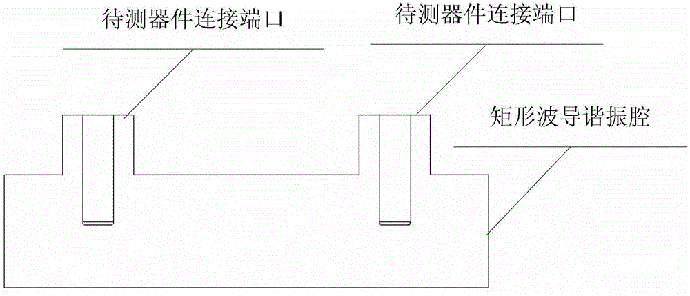
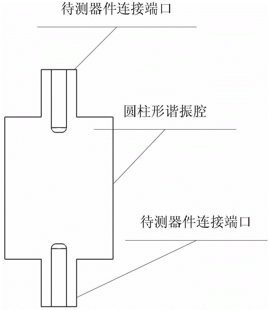
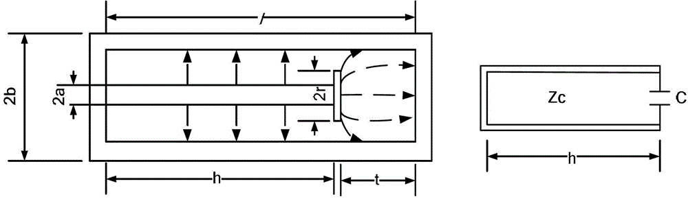
[0053] According to the specific implementation methods of the above four points, the test platform was designed and processed, and the test of the 162.5MHz high-power input coupler was completed. The basic physical structure dimensions of the test platform are as follows: a=100mm; b=200mm; r=180mm; l=180mm; h=145mm. The outer conductor of the two devices under test—"162.5MHz high-power input coupler" is connected to the large straight tube 6 at the connection port of the device under test through flange sealing, and the inner conductor is connected to the small straight tube 7 at the connection port of the device under test through Plug structure tight fit connection. The measured VSWR of the entire test platform is less than 1.1, which better meets the requirements of power matching transmission; the power test level reaches 20kW continuous wave, which meets the power design index of the device under test.

Embodiment 2325

[0054] Example 2325MHz High Power Input Coupler Test

[0055]According to the specific implementation methods of the above four points, the test platform was designed and processed, and the test of the 325MHz high-power input coupler was completed. The basic physical structure dimensions of the test platform are as follows: a=100mm; b=200mm; r=180mm; l=180mm; h=80mm. The outer conductor of the two devices under test—"325MHz high power input coupler" is connected to the large straight tube 6 at the connection port of the device under test through a flange sealing connection, and the inner conductor and the small straight tube 7 at the connection port of the device under test are connected through a plug Plug structure tight fit connection. The measured VSWR of the entire test platform is less than 1.1, which satisfies the requirements of power matching transmission; the power test level reaches 10kW continuous wave, which meets the power design index of the device under test.


PUM


Abstract

The invention discloses a high-power microwave testing platform. The high-power microwave testing platform comprises a tubular outer conductor (2) and a tubular inner conductor (1) located in the tubular outer conductor (2), wherein an upper port of the outer conductor (2) is in sealing connection with an upper end cover (3). An upper port of the inner conductor (1) is in sealing connection with a flat plate (5), and a lower port of the inner conductor (1) and a lower port of the outer conductor (2) are in sealing connection with a lower end cover (4). The tubular inner conductor (1), the tubular outer conductor (2), the upper end cover (3) and the lower end cover (4) form a coaxial resonant cavity, and a parallel plate capacitor is formed between the flat plate (5) and the upper end cover (3). The upper end cover (3) is provided with two to-be-detected device connecting ports. The testing of low-frequency, intermediate-frequency and high-frequency devices can be achieved by adjusting platform parameters, and the high-power microwave testing platform has the advantages of being small in size, wide in working frequency bandwidth and easy to adjust.

Description

technical field [0001] The invention relates to a high-power microwave test platform, which belongs to the microwave field. Background technique [0002] High power microwave testing is a highly specialized technology in the microwave field. In the superconducting high-frequency field of particle accelerators, common high-power microwave devices include high-power input couplers, high-order mode absorbers, superconducting accelerating cavities, etc. The high-power testing of these devices has two characteristics of high vacuum and high power, so A special test bench is required. The platform needs to undertake the functions of establishing microwave matching transmission path, establishing high vacuum environment and providing support at the same time. [0003] At present, the high-power test platforms of accelerator high-frequency laboratories at home and abroad usually use rectangular resonators [Document 1, M.Stirbet., I.E.Campisi, G.K.Davis, M.Drury, T.Powers, G.Myneni...

Claims


Application Information

Patent Timeline
Patent Type & Authority Patents(China)
IPC IPC(8): H01P7/04G01R31/00
Inventor 黄彤明马强潘卫民孟繁博陈旭林海英赵光远
Owner INST OF HIGH ENERGY PHYSICS CHINESE ACAD OF SCI
Why Eureka
Try Eureka