Automatic thoracentesis suction device

A suction device and automatic technology, applied in the direction of puncture needles, suction instruments, trocars, etc., can solve problems such as unstable pressure, suction of connecting tubes, accidental injury to internal organs in the thoracic cavity, etc., to achieve easy and reliable fixation, prevent accumulated The effect of preventing liquid pollution and avoiding accidental injury to patients

Inactive Publication Date: 2013-11-20
AFFILIATED HOSPITAL OF NANTONG UNIV
View PDF5 Cites 1 Cited by
  • Summary
  • Abstract
  • Description
  • Claims
  • Application Information

AI Technical Summary

Problems solved by technology

prone to counting errors due to sometimes memory errors, sometimes mixed with foam
The size of the suction negative pressure is completely adjusted by the operator through the control of the syringe. The pressure is unstable. If the negative pressure is too small, the suction may not be possible. Sliding lung causing injury
Vibration of the needle due to suction action can also lead to accidental injury to internal thoracic organs

Method used


Image

  • Automatic thoracentesis suction device
  • Automatic thoracentesis suction device
  • Automatic thoracentesis suction device

Examples


Embodiment 1

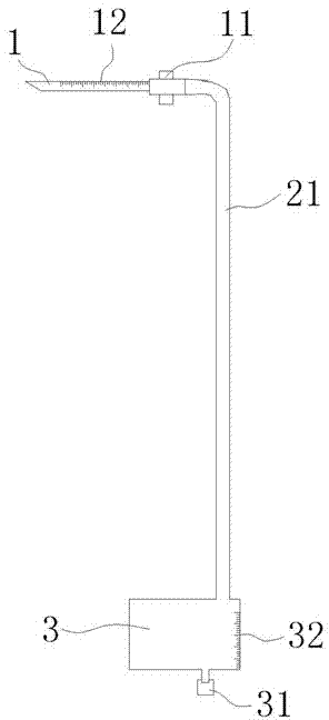
[0027] figure 1 Schematically shows the automatic chest puncture suction device according to the first embodiment of the present invention.

[0028] Such as figure 1 As shown, the automatic suction device for thoracic puncture of the present invention includes: a puncture needle 1 and a liquid column pressure suction device 2 , and the liquid column pressure suction device 2 includes a drainage tube 21 and a liquid storage device 3 . The drainage tube 21 is connected to the tail end of the puncture needle 1, and the liquid storage device 3 is connected to the end of the drainage tube 21 that is not connected to the puncture needle 1. The liquid storage device 3 is a cavity, and the bottom of the liquid storage device 3 is provided with a liquid discharge port 31 . The liquid column pressure suction device 2 is arranged vertically, and the liquid column pressure suction device 2 is lower than the puncture needle 1 .

[0029] A depth scale mark 12 is provided on the surface o...

Embodiment 2

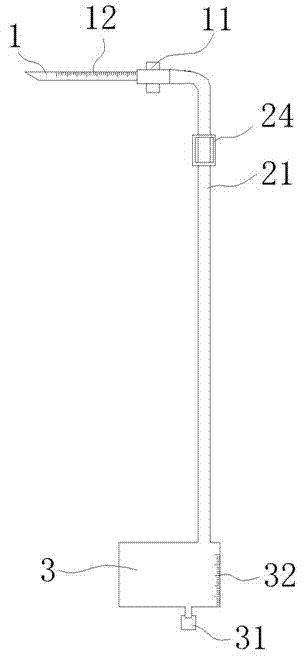
[0038] figure 2 A thoracic automatic suction device according to the second embodiment of the present invention is schematically shown.

[0039] Such as figure 2 As shown, the thoracic automatic suction device of the present invention includes: a puncture needle 1 and a liquid column pressure suction device 2 , and the liquid column pressure suction device 2 includes a drainage tube 21 , a negative pressure suction device and a liquid storage device 3 . The drainage tube 21 is connected to the tail end of the puncture needle 1; the negative pressure suction device is a fastening clip 24, and two fastening clips 24 are arranged on the drainage tube 21; the liquid storage device 3 is connected to the drainage tube 21 and not connected to the puncture needle 1 At one end of the connection, the liquid storage device 3 is a cavity, and the bottom of the liquid storage device 3 is provided with a liquid discharge port 31 . The liquid column pressure suction device 2 is arranged ...

Embodiment 3

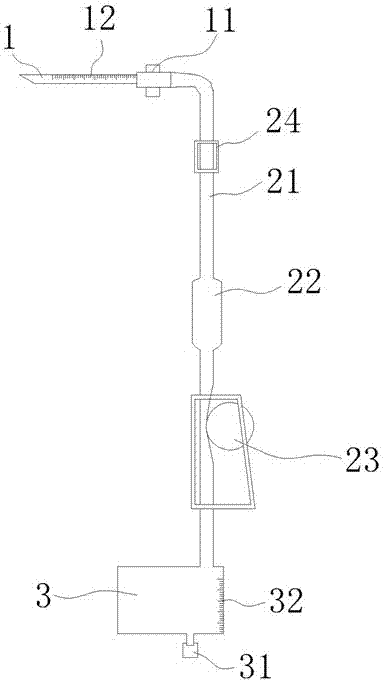
[0050] image 3 A thoracic automatic suction device according to the second embodiment of the present invention is schematically shown.

[0051] Such as image 3 As shown, the automatic chest puncture suction device of the present invention includes: a puncture needle 1 and a liquid column pressure suction device 2, the liquid column pressure suction device 2 includes a liquid storage device 3 and a flow regulating device, and the flow regulating device includes: a liquid storage device Capsule 22 and flow regulator 23. The liquid column pressure suction device 2 is arranged vertically, and the liquid column pressure suction device 2 is lower than the puncture needle 1 .

[0052] The liquid column pressure suction device 2 includes: a drainage tube 21 connected to the tail end of the puncture needle 1, and the middle part of the drainage tube 21 is sequentially connected with a fastening clip 24, a liquid storage bag 22 and a The flow regulator 23 is connected to the liquid s...


PUM


Abstract

The invention provides an automatic thoracentesis suction device which comprises a puncture needle. The automatic thoracentesis suction device is characterized in that a liquid-column pressure suction device is connected onto the puncture needle, is arranged vertically and is lower than the puncture needle. The automatic thoracentesis suction device has the advantages that the automatic thoracentesis suction device can be operated easily and conveniently and is convenient and sanitary, labor is saved, fatigue of operators is prevented owing to the fact that hydrops are automatically sucked under the negative pressure, the hydrops can be prevented from being contaminated, environments can be prevented from being polluted by the hydrops, and patients are prevented from being accidentally injured.

Description

technical field [0001] The invention relates to the technical field of medical devices, in particular to an automatic chest puncture suction device for preventing pollution. Background technique [0002] At present, when the fluid is extracted during the operation, two people are required to cooperate. A thoracentesis was performed by one person, and the pleural effusion was aspirated through an interpreter. After filling the syringe with fluid, the syringe needs to be separated from the drainage tube to remove the fluid. In order to prevent open pneumothorax caused by venting the chest cavity, or fluid outflow, another person needs to clamp the drainage tube connected to the puncture needle through a hemostat. After the syringe is emptied, the drainage tube is connected again, and the other person releases the hemostat, draws the fluid again, and so on. [0003] This method is cumbersome to operate and requires two people to work together, and the work efficiency is low; ...

Claims


Application Information

Patent Timeline
Patent Type & Authority Applications(China)
IPC IPC(8): A61M1/00A61B17/34
Inventor 史加海高福民吴洪磊樊兴娟刘俊华尤庆生
Owner AFFILIATED HOSPITAL OF NANTONG UNIV
Why Eureka
Try Eureka