
Gantry machining lathe

A technology for processing machine tools and gantry, which is applied to metal processing machinery parts, metal processing equipment, manufacturing tools, etc. It can solve the problems of abnormal temperature rise of rolling bearings, abnormal temperature rise of cylindrical roller bearings, and poor lubricant discharge, etc., to achieve Avoid micro-centrifugation, good centering performance, good centering performance effect

Active Publication Date: 2015-06-03
JIANGSU JIANGHAI MACHINE TOOLS GROUP
View PDF5 Cites 0 Cited by
  • Summary
  • Abstract
  • Description
  • Claims
  • Application Information

AI Technical Summary

Problems solved by technology

[0005] In such a bearing, the discharge performance of the lubricant is likely to deteriorate, causing abnormal temperature rise of the cylindrical roller bearing; when performing grease lubrication, after the grease is sealed into the bearing, in order to make the sealed grease evenly inside the bearing, The so-called test run is indispensable in order to spread the remaining grease along the periphery of the bearing.
Therefore, the discharge performance of the lubricant tends to deteriorate, and the trial run takes a long time
Moreover, under high temperature conditions, the neutrality of the bearing becomes worse, which reduces the machining accuracy
[0006] Therefore, the problem to be solved in the prior art is that in the case of too much lubricant, the rolling bearing is prone to abnormal temperature rise, and maintains good centering during high-speed motion

Method used


Image

  • Gantry machining lathe
  • Gantry machining lathe
  • Gantry machining lathe

Examples


Embodiment Construction

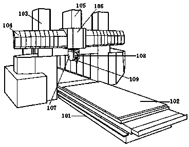
[0030] see figure 1 , shows the gantry processing machine tool of the present invention.

[0031] The gantry processing machine tool includes a machine platform 101 and a worktable 102 that can slide back and forth on the machine platform 101. Columns 103 are respectively arranged on both sides of the rear end of the machine platform 101, and a vertical moving part 104 is movably arranged on the On the column 103, a driving part (not shown) can drive the vertical moving part 104 to move vertically on the column 103. Optionally, the vertical moving part 104 is a horizontal column.

[0032] The vertical moving part 104 is provided with a left and right moving part 106 that can move left and right, and the left and right moving part 106 is provided with a power part 105 that can drive it to move, thus, through the workbench that can move back and forth, it can vertically The vertical moving part that moves, and the left and right moving part that can move left and right realize ...


PUM


Abstract

The invention discloses a gantry machining lathe. The gantry machining lathe comprises a lathe table and a worktable capable of sliding front and back on the lathe table, wherein stand pillars are respectively arranged at two sides of the rear end of the lathe table, a vertical motion part is movably arranged on the stand pillars, a left-right motion part capable of moving left and right is arranged on the vertical motion part, a machining head capable of swinging front and back is arranged at the lower end of the left-right motion part and comprises a main shaft component and a cutter driven by the main shaft component to rotate, the main shaft component comprises a main shaft located inside an outer shell, a first bearing component is arranged between the front end of the main shaft and the outer shell, a second bearing component is arranged between the rear end of the main shaft and the outer shell, and a lubricating liquid supply part supplies lubricating oil through a lubrication liquid pipeline. The gantry machining lathe is simple in structure, is good in lubricating effect, avoids abnormal temperature rise of the main shaft, provides centering auxiliary performance, and guarantees the smoothness and accuracy of machining.

Description

technical field [0001] The invention relates to the technical field of processing machine tools, in particular to a high-precision, leak-proof gantry processing machine tool. Background technique [0002] Commonly used machine tools are equipped with a main shaft that fixedly supports the tool for rotation, and various cutting processes can be performed by installing various tools on the tool holder at the front end of the main shaft of the machine tool in the axial direction. [0003] In the existing machine tools, the tool holder has a movable clamping unit for releasably clamping the tool shank and an action unit for moving the movable clamping unit between the shank release position and the shank clamping position, and is housed in The axial direction through hole of the main shaft. The operating unit of the tool holding mechanism is driven by a drive mechanism (for example, a hydraulic cylinder mechanism) outside the spindle head device, and moves the movable clamping ...

Claims


Application Information

Patent Timeline
Patent Type & Authority Patents(China)
IPC IPC(8): B23B19/02B23Q11/12
Inventor 康铁强陈友华
Owner JIANGSU JIANGHAI MACHINE TOOLS GROUP
Features
  • Generate Ideas
  • Intellectual Property
  • Life Sciences
  • Materials
  • Tech Scout
  • Unparalleled Data Quality
  • Higher Quality Content
  • 60% Fewer Hallucinations
Learn More