Slotting duct propeller systems and hovercar applying same

A technology of flying cars and propellers, applied in the field of ducts, can solve the problems of not using flying cars, etc., achieve the effect of smooth conversion and increase the lift of ducts

Inactive Publication Date: 2013-11-20
李凤
View PDF7 Cites 31 Cited by
  • Summary
  • Abstract
  • Description
  • Claims
  • Application Information

AI Technical Summary

Problems solved by technology

This folding action is very clever, bu

Method used


Image

  • Slotting duct propeller systems and hovercar applying same
  • Slotting duct propeller systems and hovercar applying same
  • Slotting duct propeller systems and hovercar applying same

Examples


Embodiment Construction

[0025] The present invention will be further described in detail below in conjunction with the accompanying drawings and embodiments.

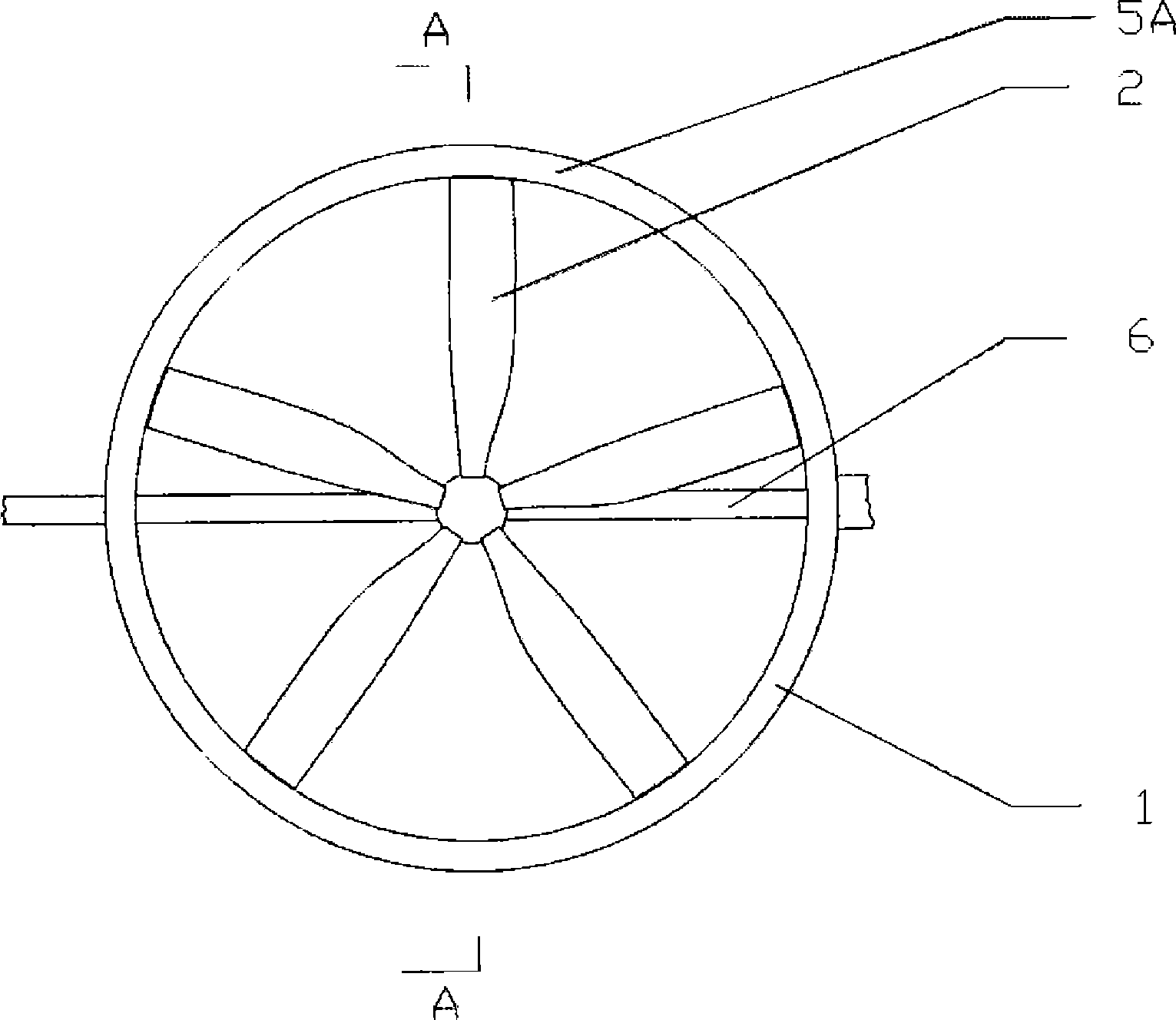
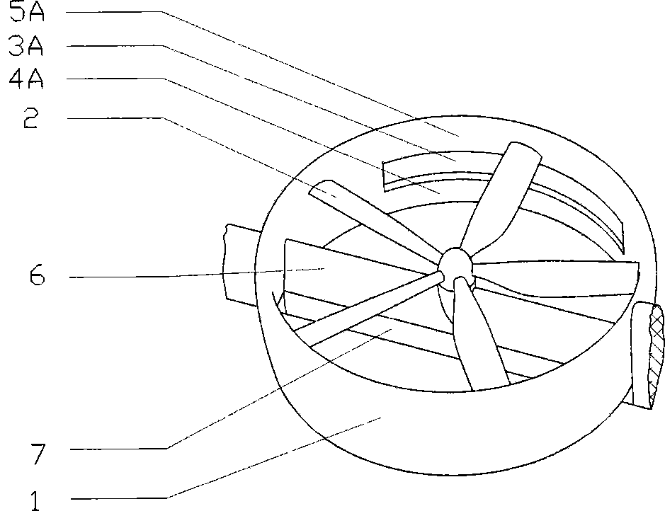
[0026] Such as figure 1 , 2 , 3, 4, 5, 6, 7 and 8, the slotted ducted propeller system in this embodiment includes a duct 1 and a propeller 2 arranged in the duct, when the duct 1 and the propeller 2 are in a horizontal propulsion attitude, On the upper part of the duct 1, there is a slot that connects the surface of the inner wall of the duct 1 and the surface of the outer wall. The opening of the inner wall of the slot is located behind the plane of rotation of the propeller 2. The slot extends from the inner wall to the outer wall to the rear edge to reduce the propeller. 2 Friction loss of the slipstream flowing from the inner wall of the duct 1 to the outer wall through the slot; there is a controllable mechanism on the inner wall of the duct 1 to control the closing and opening of the slot, so that it is closed when the duct 1 is in an ...


PUM


Abstract

The invention discloses slotting duct propeller systems. In each slotting duct propeller system, the upper portion of a duct is provided with a seam communicated with an inner wall surface and an outer wall surface of the duct, the inner wall of the duct is provided with a controllable mechanism for controlling closing and opening of the seam, so that the seam is closed when the duct is in an approximately horizontal posture and vertical take-off and landing are carried out, so as to reduce a friction resistance of a propeller slipstream in the inner wall and reduce the loss of a direct lift force; the seam is opened when the duct tilts to an approximately perpendicular beneficial incidence angle posture and horizontal flight is carried out, lift augmentation of power is carried out, so as to increase a duct lift force. A hovercar applying the slotting duct propeller systems is provided with folding mechanisms, locking mechanisms and tilting mechanisms, so that the hovercar can be changed between a car status and an aircraft status, and the hovercar can perform vertical take-off and landing in the aircraft status and flies at a high speed.

Description

technical field [0001] The invention relates to a duct, in particular to a slotted ducted propeller system and a flying car using the slotted ducted propeller system. Background technique [0002] The currently known ducted propellers and ducted fans all adopt flat and common cylindrical ducts. Since the chord length is small, and the leading and trailing edges are circular, it is inconvenient to install an increasing device. To generate direct lift in a horizontal attitude for vertical take-off and landing, it is necessary to use a small angle of attack to generate lift when flying horizontally. Since the ducts basically use symmetrical airfoils, the lift is limited when flying horizontally; The size of the duct means that the diameter and height of the duct are strictly limited, so only a not too large duct can be used, thereby making the duct less lift when flying horizontally. [0003] In 2012, Trafuja Company of the United States launched a flying car called "Leap" inv...

Claims


Application Information

Patent Timeline
IPC IPC(8): B64C11/00B60F5/02
Inventor 龙川
Owner 李凤
Why Eureka
Try Eureka