

High- and low-sill stilling basin with function of on-way dispersive energy dissipation
A technology of decentralized energy dissipation and stilling pools, applied in water conservancy projects, marine engineering, coastline protection, etc., can solve problems such as large water surface fluctuations and severe water flow turbulence, achieve horizontal vortex relief, protect safety, and avoid air pollution. The effect of cavitation erosion
- Summary
- Abstract
- Description
- Claims
- Application Information
AI Technical Summary
Problems solved by technology
Method used
Image

Examples
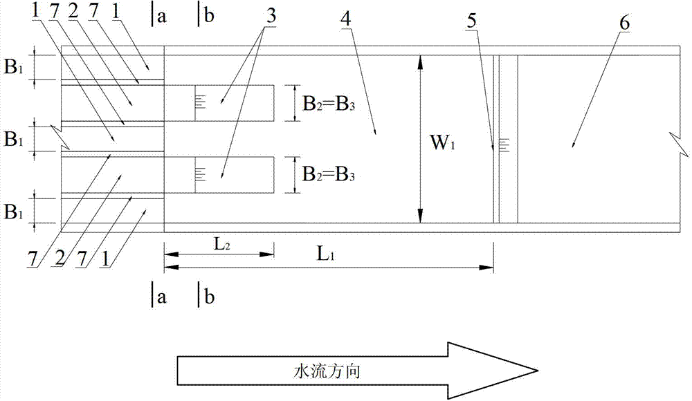
Embodiment 1
[0060] Example 1 and figure 1 The difference is that when the holes on both sides are high ridges, the number of holes in the high ridge discharge hole 1 is N 1 is 6, the number of holes N of the low sill discharge hole 2 2 is 5, the number of partition walls 3 in the stilling pool N 3 for 5.
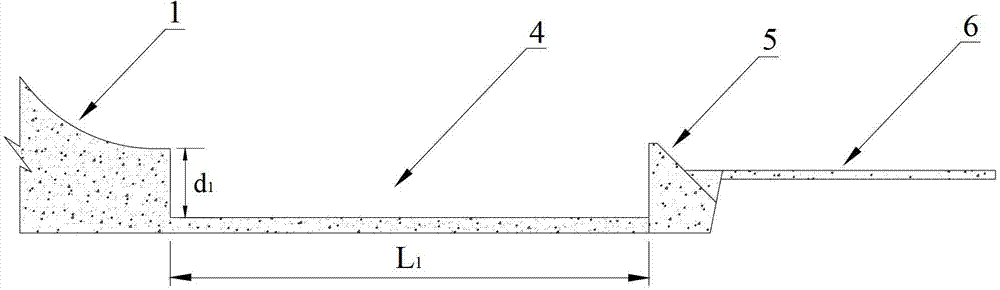
[0061] The relevant structural parameters of the high and low sill stilling pools for scattered energy dissipation along the process described in Embodiment 1 are as follows: the width W of the stilling pool 4 1 is 108m, the length L of stilling basin 4 1 is 228m, the length L of the partition wall 3 in the stilling pool 2 is 57m, the width B of the high sill discharge hole 1 1 is 6m, the width B of the low sill discharge hole 2 2 is 8m, the width B of the partition wall 3 in the stilling pool 3 is 8m, the height d from the outlet end of the high sill discharge hole 1 to the bottom plate of the stilling basin 1 is 16m, the height d from the outlet end of the low sill discharge h...
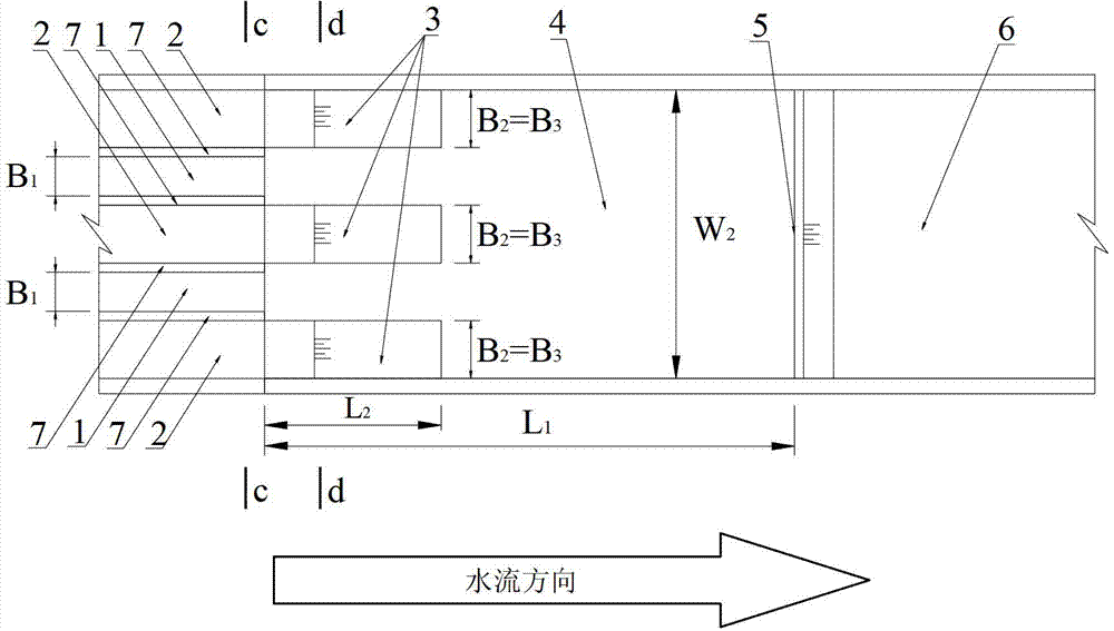
Embodiment 3
[0065] Example 3 and figure 2 The difference is the hole number N of the high sill discharge hole 1 1 is 5, the number of holes N of the low sill discharge hole 2 2 is 6, the number of partition walls 3 in the stilling pool N 3 for 6.
[0066] The relevant structural parameters of the high and low sill stilling pools for scattered energy dissipation along the process described in Embodiment 3 are as follows: the width W of the stilling pool 4 2 is 110m, the length L of the stilling basin 4 1 is 228m, the length L of the partition wall 3 in the stilling pool 2 is 57m, the width B of the high sill discharge hole 1 1 is 6m, the width B of the low sill discharge hole 2 2 is 8m, the width B of the partition wall 3 in the stilling pool 3 is 8m, the height d from the outlet end of the high sill discharge hole 1 to the bottom plate of the stilling basin 1 is 16m, the height d from the outlet end of the low sill discharge hole 2 to the bottom plate of the stilling basin 2 is ...
PUM
 Abstract
Description
Claims
Application Information