External-installed triggering type anti-sink device

An anti-falling and triggering technology, which is applied in the directions of construction, housing structure support, scaffolding supported by housing structure, etc., can solve the problems of increased processing and installation costs, dismantling of the anti-fall device 100, low reliability, etc. Cost of machining and installation, improved safety and reliability, effect of wide range of clearance adjustment

Pending Publication Date: 2017-05-17
厦门安科科技有限公司
View PDF6 Cites 7 Cited by
  • Summary
  • Abstract
  • Description
  • Claims
  • Application Information

AI Technical Summary

Problems solved by technology

[0004] The first is the steel suspension rod type fall arrester, which is easily affected by installation and wear of the steel suspension rod, resulting in excessive fall prevention distance or even failure;
[0005] The second is the star-wheel type anti-fall device, which is equipped with a return spring, which is easily affected by the erosion of cement and mortar on site and the fatigue strength of the spring itself, resulting in potential safety hazards and even failure;
[0006] The third is the planetary jamming anti-falling device, which uses the star wheel and the eccentric pendulum block to cooperate. When the lifting scaffold falls sharply, the eccentric pendulum block cannot recover in time because the star wheel rotates too fast, and the eccentric pendulum block is stuck upward by the blocking rod. Block and block the star wheel downward to further prevent the elevating scaffold from continuing to fall, and play a role in preventing falling; however, this device has many defects: (1) It is necessary to specially set the blocking bar, which increases the cost of components and the cost of processing and installation Increase, the structure is not compact, and the installation is inconvenient; (2) The eccentric pendulum block is a "character-eight" shaped eccentric wheel, which completely relies on self-resetting, so it is difficult to maintain the same position after reset, and it is very easy to produce the center of gravity due to the adhesion of cement and mortar on site The deviation affects the normal operation of the device; (3) The swing range of the eccentric pendulum block is large and unstable during the movement process, which further makes the structural design not compact; (4) In the falling condition, only the teeth of the star wheel and the eccentric pendulum The point-surface contact formed between the lower ends of one side of the block blocks the star wheel, and the reliability is low. It is very easy to shift the center of gravity due to the adhesion of cement and mortar on site, resulting in poor or no contact between the point-surface and the device failure.
[0008] This installation structure has the following defects: First, the fall arrester 100' cannot be completely disassembled from the wall-attached frame 42' after installation, and the lifting of the frame body 50 and the disassembly of the fall arrester 100' must be completed in at least three steps; The first step is as Figure 4 As shown, first promote the frame body 50 to the bottom of the frame body 50 beyond the bottom fall arrester 100 ', the second step is as follows Figure 5 As shown, remove the lowermost fall arrester 100' and install it on the upper part of the frame body 50, the third step is as follows Image 6 As shown, continue to lift the frame body 50 to the specified position; in this way, the frame body 50 is lifted in sections, and the lifting needs to be stopped in the middle to disassemble the fall arrester 100', and the fall arrester 100' cannot be disassembled before the frame body 50 is lifted. , the disassembly operation is troublesome, resulting in time-consuming and labor-intensive lifting, which directly affects the construction efficiency; second, the deviation caused by the non-vertical installation of the upper and lower fall arresters 100' at the same machine position cannot be eliminated, resulting in abnormal lifting force

Method used


Image

  • External-installed triggering type anti-sink device
  • External-installed triggering type anti-sink device
  • External-installed triggering type anti-sink device

Examples


Embodiment Construction

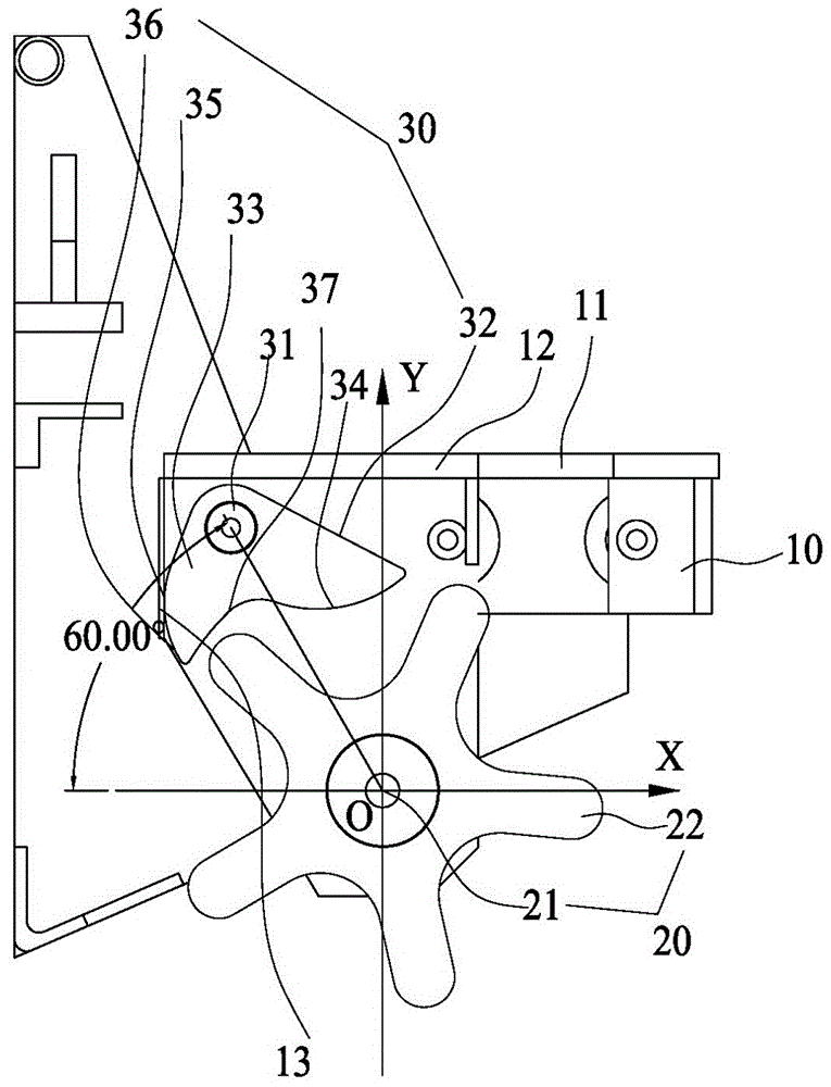
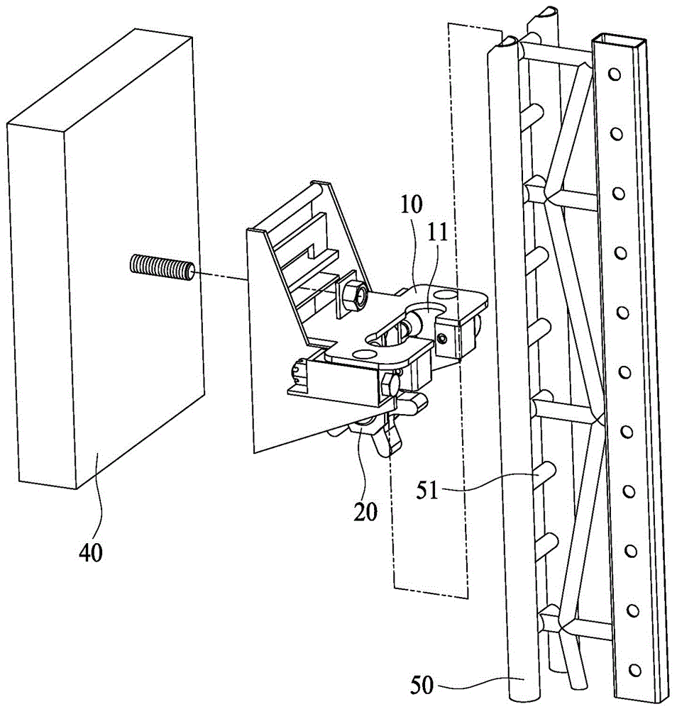
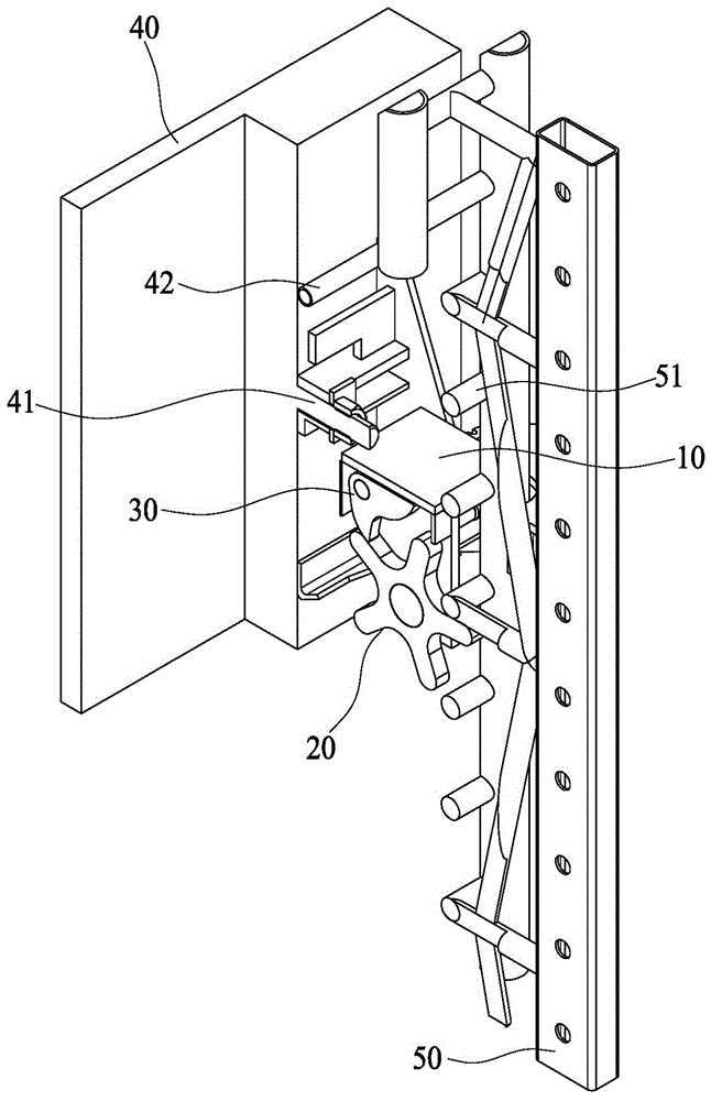
[0070] see Figure 1 to Figure 19 As shown, an external trigger type fall arrester 100 disclosed in the present invention has a base 10 with a lifting rail 11 guiding it.

[0071] The multi-claw rotor 20 is rotatably installed in the base body 10 through a pin shaft 21 . The so-called multi-claw rotor 20 may have 4-6 claws 22 evenly arranged.

[0072] The special-shaped clip 30 is rotatably installed in the base body 10 through a pin shaft 31 . The special-shaped clip 30 has a transmission part 32 and a brake part 33 arranged in an L shape. One end of the transmission part 32 and the brake part 33 near the pin shaft 31 is connected together, and the other end extends to the distance respectively. The inner surface of the transmission part 32 The arc counterweight 34 is formed by arching. Correspondingly, the outer surface corresponding to the transmission part 32 on the base body 10 forms an upper limit plate 12 for limiting the upward rotation of the special-shaped clip 30...


PUM


Abstract

The invention discloses an external-installed triggering type anti-sink device. The external-installed triggering type anti-sink device comprises a base body with a lifting rail for guiding; a multi-claw rotor and a special-shaped clamp are rotatably installed in the base body through a pin shaft, a transmission part and a braking part which are in an L shape are installed on the special-shaped clamp, and the ends, close to the pin shaft, of the transmission part and the braking part are connected together, and the other ends of the transmission part and the braking part extend towards a distant place; an arc-shaped balance weight is formed by hunching up of the inner side face of the transmission part, an upper limiting plate used for limiting upwards rotating of the special-shaped clamp is formed on the position, corresponding to the outer side face of the transmission part, of the base body, and a side limiting face used for limiting downwards rotating of the special-shaped clamp is formed on the position, corresponding to the outer side face of the braking part, of the base body; and when the multi-claw rotor rotates, claws make sliding-matched movement along an arc-shaped track of the arc-shaped balance weight so that the special-shaped clamp can be pushed to deflect, and when the special-shaped clamp deflects to the outer side face of the transmission part and abuts against the upper limiting plate, the outer side face of the braking part abuts against the claws of the multi-claw rotor and limit rotation of the multi-claw rotor. According to the external-installed triggering type anti-sink device, the structure is simple and compact, and safety and reliability are high.

Description

technical field [0001] The invention relates to an external trigger type fall arrester, which is suitable for an attached lifting scaffold. Background technique [0002] The attached lifting scaffold is a scaffold built along the outer surface of the building structure. It is a new type of scaffolding technology developed rapidly at the beginning of this century. Low-carbon, high-tech content and more economical, safer and more convenient features. The lifting function of the attached lifting scaffold greatly facilitates the construction work of building construction and decoration engineering. The lifting scaffold also has an anti-tilt device and an anti-fall device. Among them, the anti-fall device can ensure that the lifting scaffold is always in a safe state and effectively prevents falling, which is the key to safe construction. [0003] In the prior art, there are three kinds of anti-fall devices: [0004] The first is the steel suspension rod type fall arrester, w...

Claims


Application Information

Patent Timeline
Patent Type & Authority Applications(China)
IPC IPC(8): E04G3/32
CPCE04G3/32
Inventor 施志峰王化峰高镜钦
Owner 厦门安科科技有限公司
Why Eureka
Try Eureka