
Dispersed high and low sill stilling pools for energy dissipation along the route

A technology of dispersed energy dissipation and stilling pool, applied in water conservancy engineering, marine engineering, coastline protection, etc., can solve the problems of severe water turbulence and large fluctuation of water surface, to protect safety, improve stress conditions, and avoid empty space. The effect of cavitation

Active Publication Date: 2015-08-26
CHINA THREE GORGES CORPORATION
View PDF7 Cites 1 Cited by
  • Summary
  • Abstract
  • Description
  • Claims
  • Application Information

AI Technical Summary

Problems solved by technology

[0009] The problem to be solved by the present invention is to provide a stilling basin that overcomes the limitations of the above-mentioned prior art and effectively solves unfavorable hydraulic problems that may occur during safe and stable operation, so as to reduce and homogenize the flow rate of the stilling basin to the front section of the stilling basin. Disperse the concentrated energy dissipation area in the first half of the high and low sill stilling pool, achieve the effect of dispersed energy dissipation along the way, and eliminate the phenomenon of severe water flow turbulence and large water surface fluctuations in the concentrated energy dissipation area

Method used


Image

  • Dispersed high and low sill stilling pools for energy dissipation along the route
  • Dispersed high and low sill stilling pools for energy dissipation along the route
  • Dispersed high and low sill stilling pools for energy dissipation along the route

Examples


Embodiment 1

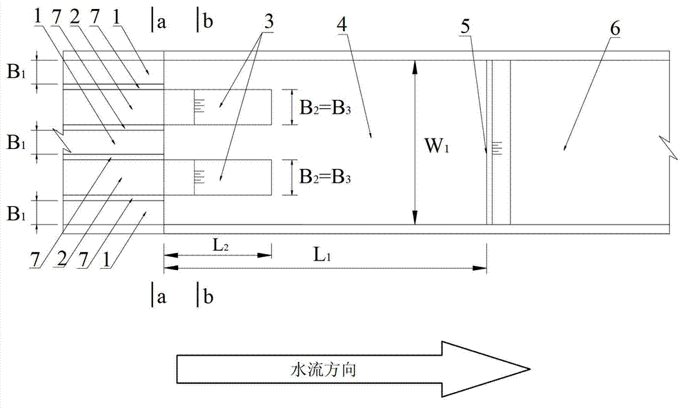
[0056] Example 1 and figure 1 The difference is that when the holes on both sides are high ridges, the number of holes in the high ridge discharge hole 1 is N 1 is 6, the number of holes N of the low sill discharge hole 2 2 is 5, the number of partition walls 3 in the stilling pool N 3 for 5.

[0057] The relevant structural parameters of the high and low sill stilling pools for scattered energy dissipation along the process described in Embodiment 1 are as follows: the width W of the stilling pool 4 1 is 108m, the length L of stilling basin 4 1 is 228m, the length L of the partition wall 3 in the stilling pool 2 is 57m, the width B of the high sill discharge hole 1 1 is 6m, the width B of the low sill discharge hole 2 2 is 8m, the width B of the partition wall 3 in the stilling pool 3 is 8m, the height d from the outlet end of the high sill discharge hole 1 to the bottom plate of the stilling basin 1 is 16m, the height d from the outlet end of the low sill discharge h...

Embodiment 3

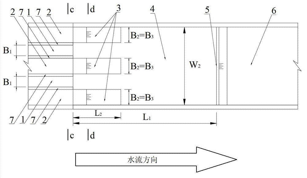
[0061] Example 3 and figure 2 The difference is the hole number N of the high sill discharge hole 1 1 is 5, the number of holes N of the low sill discharge hole 2 2 is 6, the number of partition walls 3 in the stilling pool N 3 for 6.

[0062] The relevant structural parameters of the high and low sill stilling pools for scattered energy dissipation along the process described in Embodiment 3 are as follows: the width W of the stilling pool 4 2 is 110m, the length L of the stilling basin 4 1 is 228m, the length L of the partition wall 3 in the stilling pool 2 is 57m, the width B of the high sill discharge hole 1 1 is 6m, the width B of the low sill discharge hole 2 2 is 8m, the width B of the partition wall 3 in the stilling pool 3 is 8m, the height d from the outlet end of the high sill discharge hole 1 to the bottom plate of the stilling basin 1 is 16m, the height d from the outlet end of the low sill discharge hole 2 to the bottom plate of the stilling basin 2 is ...


PUM


Abstract

The invention relates to a high- and low-sill stilling basin with a function of on-way dispersive energy dissipation. The high- and low-sill stilling basin comprises a flow inlet segment, a stilling basin connected with the flow inlet segment, stilling basin inner partitions, a stilling basin end sill and an apron connected with the stilling basin, wherein the stilling basin inner partitions connected with the inlet segment locate at the front end of the stilling basin. The partitions are distributed at intervals at the position of the high- and low-sill stilling basin, connected with low-sill discharge holes. The bottom of each partition locates on the bed of the stilling basin. The two sides and upstream rectangular side of each partition are all perpendicular to the bed of the stilling basin, and from the top of an outlet of the low-sill discharge hole of the flow inlet segment, the partitions are smoothly connected with a low sill through arc transitional segments. The high- and low-sill stilling basin has the advantages that the impact of discharge flow upon the front of the stilling basin can be dissipated and homogenized, the central energy-dissipating area in the front half of the high- and low-sill stilling basin is dispersed, the on-way dispersive energy dissipation is achieved, the problems of turbulent and violent flows and high surface fluctuation in the central energy-dissipating area are avoided, horizontal axial vortexes are effectively cut off, and damage of the horizontal axial vortexes is further weakened.

Description

technical field [0001] The invention relates to the technical field of low atomization and high-efficiency energy dissipation for flood discharge with high water head and large single-width flow rate in water conservancy and hydropower projects, in particular to a stilling pool with high and low sills for energy dissipation scattered along the course. Background technique [0002] The problem of flood discharge and energy dissipation with high water head and large single wide flow is a difficult and crucial problem in water conservancy projects. [0003] The patent with publication number CN101215828A proposes a high and low bottom flow stilling pool, and the patent with publication number CN101624818A improves the high and low bottom flow stilling pool by adopting a differential split inlet, including a water flow inlet section, and The stilling basin connected to the inlet section of the water flow, and the apron connected to the stilling basin. [0004] The energy dissip...

Claims


Application Information

Patent Timeline
Patent Type & Authority Patents(China)
IPC IPC(8): E02B8/06
Inventor 牛志攀张超然李晶华尹庭伟朱红兵惠二青
Owner CHINA THREE GORGES CORPORATION
Learn More