Connected node of concrete filled steel tube combination column and reinforced concrete beams

A technology of reinforced concrete beams and steel pipe concrete, which is applied in the direction of architecture and building construction, and can solve the problems of high accuracy requirements for reinforcement ring design and construction manufacturing, difficulty in meeting anchorage length requirements, and affecting the shape of building facades, etc. To achieve the effect of direct force transmission, tight combination and simple structure

Active Publication Date: 2013-11-20
香港华艺设计顾问(深圳)有限公司
View PDF5 Cites 4 Cited by
  • Summary
  • Abstract
  • Description
  • Claims
  • Application Information

AI Technical Summary

Problems solved by technology

Although the use of reinforced concrete ring beam joints avoids the trouble of beam longitudinal bars passing through steel pipes, it also has the following disadvantages: on the one hand, the protruding joint part of the ring beam will affect the shape of the building's facade; There are conflicts with the steel bars in the column and beam sections during construction, and it is difficult to meet the anchorage length requirements. At the same time, it is diffic

Method used


Image

  • Connected node of concrete filled steel tube combination column and reinforced concrete beams
  • Connected node of concrete filled steel tube combination column and reinforced concrete beams
  • Connected node of concrete filled steel tube combination column and reinforced concrete beams

Examples


Embodiment

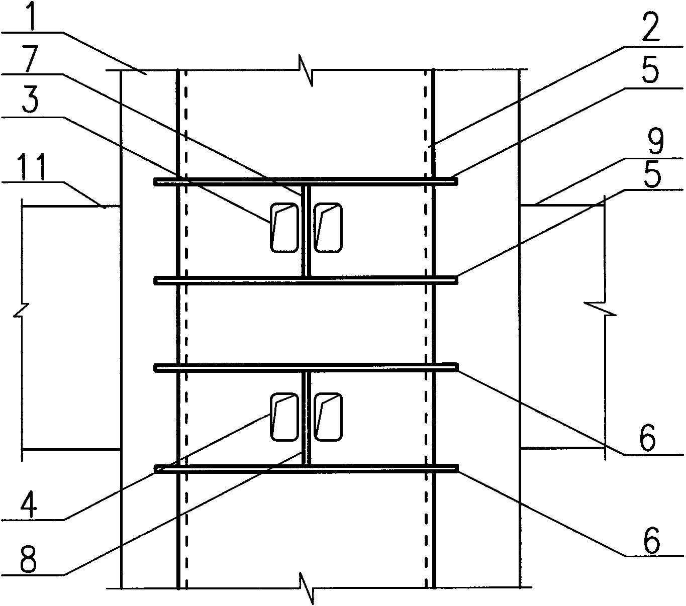
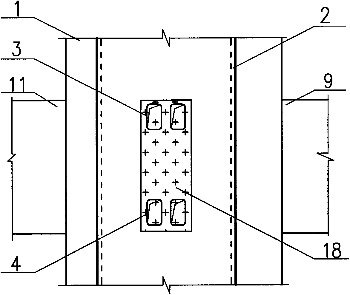
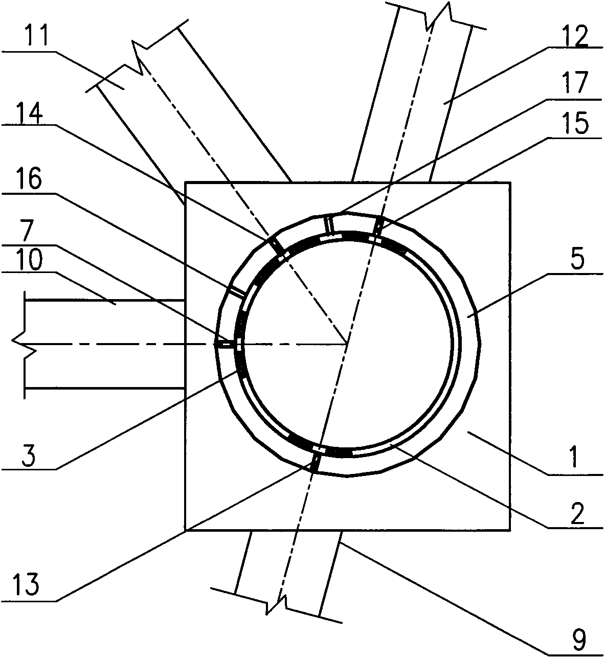
[0019] The schematic diagram of the node structure of the present invention is as figure 1 , 2 , 3, 4, 5, and 6. A steel pipe concrete composite column-reinforced concrete beam connection node of the present invention, wherein the steel pipe 2 in the steel pipe concrete composite column 1 is provided with four large square openings corresponding to each intersecting reinforced concrete beam, see figure 1 . The two upper openings 3 and the two lower openings 4 respectively correspond to the gluten and bottom bars in the longitudinal bars of the reinforced concrete beam. figure 2 The shaded area 18 represents the corresponding figure 1 The relative positions of the reinforced concrete beam sections of the middle upper opening 3 and the lower opening 4. In order to avoid stress concentration at the corner of the hole, it is required to set a round chamfer at the corner of the hole during construction, such as figure 1 shown.

[0020] image 3 Shown is the planar cutout of...


PUM


Abstract

The invention discloses a connected node of a concrete filled steel tube combination column and reinforced concrete beams. The concrete filled steel tube combination column and the reinforced concrete beams are intersected to the connected node. Open holes are formed in steel tubes, corresponding to the intersected positions of the reinforced concrete beams, of the concrete filled steel tube combination column. The upper end and the lower end of each reinforced concrete beam and the upper end and the lower end of the concrete filled steel tube combination column are respectively provided with two open holes, namely two upper end open holes and two lower end open holes. Longitudinal ribs inside reinforced concrete beams penetrate through the open holes in the tube wall and are anchored on core concrete inside the steel tubes. The positions above the upper end open holes, the positions below the upper end open holes, the positions above the lower end open holes and the positions below the lower end open holes are respectively provided with an annular reinforcing plate. Vertical reinforcing plates are arranged on the portions, between the open holes which have the same height and small gaps, of the tube wall. The concreted node of the concrete filled steel tube combination column and the reinforced concrete beams is used under the condition that multiple beams are slantly intersected to the node in a small-angle mode, and holes are closely formed in the tube wall. When the heights of the cross sections of the multiple beams are different, the beam longitudinal ribs can also penetrate through the large open holes conveniently. According to the connected node of the concrete filled steel tube combination column and the reinforced concrete beams, stress concentration between the open holes of the tube wall can be conveniently controlled, meanwhile, the hoop effect of the tube wall with the open holes is reinforced, and the anti-seismic performance of the node can be ensured.

Description

technical field [0001] The invention is a connection node of a steel pipe concrete composite column and a reinforced concrete beam used in the design and construction of a building structure engineering, and belongs to the innovative technology of the through-type connection node of a steel pipe concrete composite column and a reinforced concrete beam. Background technique [0002] Concrete-filled steel tube composite columns have the advantages of high strength and good ductility, and have been more and more used in the design of high-rise buildings. In order to ensure the seismic performance and take into account the economic requirements, high-rise buildings often prefer to use reinforced concrete beams. However, due to the existence of steel pipes, the longitudinal bars in reinforced concrete beams are difficult to be anchored in the joints of composite columns. The design of the joints between steel pipe concrete composite columns and reinforced concrete beams has becom...

Claims


Application Information

Patent Timeline
IPC IPC(8): E04B1/58
Inventor 陈勤黄俊海刘俊王兴法张伟严力军
Owner 香港华艺设计顾问(深圳)有限公司
Why Eureka
Try Eureka