
Financial self-service equipment and impeller type paper money separating device

A financial self-service equipment and banknote separation technology, which is used in devices for accepting coins, processing coins or valuable banknotes, transportation and packaging, etc. problem, to achieve the effect of high accuracy, preventing banknotes from flying off the impeller, and fast processing speed

Active Publication Date: 2013-11-20
GRG BAKING EQUIP CO LTD
View PDF6 Cites 20 Cited by
  • Summary
  • Abstract
  • Description
  • Claims
  • Application Information

AI Technical Summary

Problems solved by technology

Since the banknote detection sensor usually uses an optical through-beam sensor, when the impeller rotates, it takes a long time for the through-beam sensor to be blocked and re-conducted, resulting in a long detection processing time and affecting the processing speed of the whole machine
And, when the through-beam sensor is used for a long time, the detection accuracy is also affected because the surface is easily contaminated with dust
[0004] In addition, since the banknote detection sensor in the prior art is arranged on the passage close to the impeller, when the banknote detection sensor detects the banknote, it mainly detects that the banknote will enter the impeller, but in fact whether the banknote is fully inserted into the impeller is uncertain, so It may happen that the banknote is not fully inserted into the impeller and the impeller starts to rotate, causing the banknote to fly off the impeller or jam the banknote while being conveyed

Method used


Image

  • Financial self-service equipment and impeller type paper money separating device
  • Financial self-service equipment and impeller type paper money separating device
  • Financial self-service equipment and impeller type paper money separating device

Examples


Embodiment Construction

[0022] In order to further illustrate the impeller-type banknote separating device provided by the present invention, a further detailed introduction will be made below in conjunction with illustrations of preferred embodiments of the present invention.

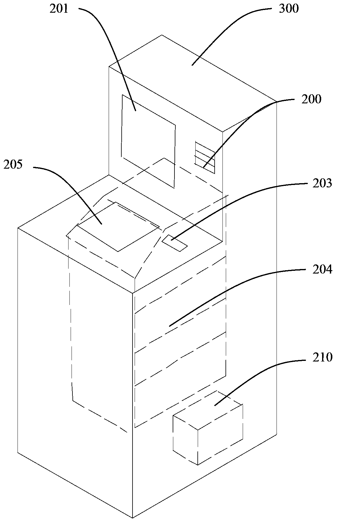
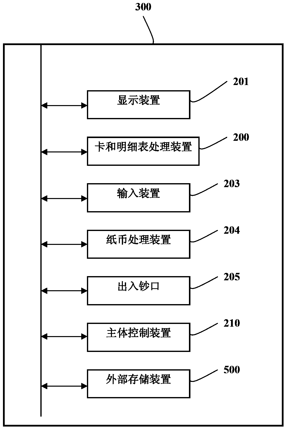
[0023] This embodiment takes the deposit machine as an example to introduce the main structure of the financial self-service equipment provided by the present invention, see figure 1 with figure 2 The ATM 300 includes: a display device 201 , a card and statement processing device 200 , an input device 203 , a banknote processing device 204 , a deposit and withdrawal port 205 , a main body control device 210 and an external storage device 500 . In addition, there are other various devices well known in the prior art, and their illustrations and descriptions are omitted.

[0024] figure 2 express figure 1 The block diagram of the control relationship of the automatic deposit and teller machine 300. The banknote processing...


PUM


Abstract

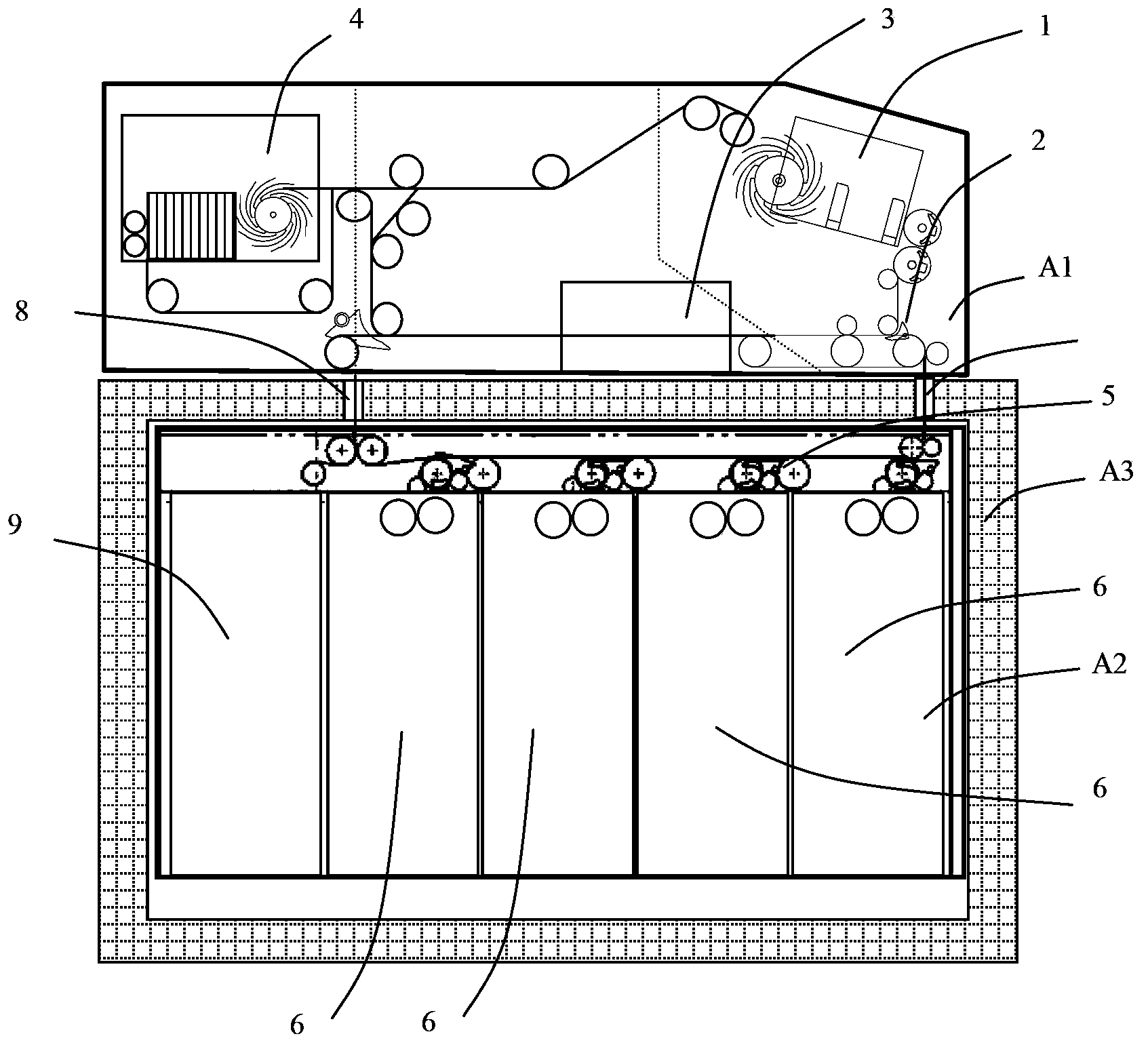
The invention relates to an impeller type paper money separating device and financial self-service equipment adopting the paper money separating device. The impeller type paper money separating device comprises a transmission impeller, an impeller phase detection sensor, a paper money transmission mechanism and at least one U-shaped sensor, wherein the transmission impeller is used for separating the paper money, at least one U-shaped sensor is fixed on the transmission impeller and is used for detecting the entering of the paper money into the transmission impeller, the U-shaped sensor comprises a signal sending end and a signal receiving end, the signal sending end and the signal receiving end are positioned at the same side of the transmission impeller, a certain gap is formed between the signal sending end and the signal receiving end for forming the opening end of the U-shaped sensor, and the opening end faces the direction of the paper money entering the impeller. Because the U-shaped sensor is adopted for detecting whether the paper money is inserted into the impeller or not for controlling the rotation of the impeller, the processing speed is higher than that of an original optical correlation sensor, in addition, the accuracy is higher, and the paper money clamping or the flying leaving of the paper money from the impeller caused by impeller rotation before the complete insertion of the paper money into the impeller can be prevented.

Description

technical field [0001] The invention relates to banknote processing equipment, in particular to an impeller-type banknote separating device and financial self-service equipment using the impeller-type banknote separating device. Background technique [0002] With the continuous development of the economy, the processing volume of banknotes is increasing, and people's requirements for the processing capacity of banknote processing equipment are also increasing. The main functions of the banknote processing equipment commonly used at present include automatic deposit and withdrawal machines, sorting machines, etc., and in these equipments, the separating device of the impeller type banknote is widely used. [0003] The separating device of the impeller type banknote mainly includes an impeller, a banknote channel, an impeller position sensor, and a detection sensor when the banknote enters the impeller. The banknote detection sensor is usually arranged on the channel close to...

Claims


Application Information

Patent Timeline
IPC IPC(8): G07D11/00
CPCB65H2301/42146B65H2301/4474B65H2301/44765B65H2511/212B65H2511/51B65H2553/81B65H2701/1912B65H43/08B65H2511/514B65H2513/512G07D11/165G07D11/40B65H29/40B65H2553/82B65H2220/01B65H2220/11B65H2220/02B65H29/22B65H2404/661
Inventor 翁秋华谭栋
Owner GRG BAKING EQUIP CO LTD
Learn More