
Dead region compensating method

A technology of dead zone compensation and compensation value, applied in the field of dead zone compensation, can solve problems such as poor voltage compensation effect

Inactive Publication Date: 2013-11-20
CHINA XD ELECTRIC CO LTD
View PDF7 Cites 6 Cited by
  • Summary
  • Abstract
  • Description
  • Claims
  • Application Information

AI Technical Summary

Problems solved by technology

[0017] The purpose of the present invention is to provide a dead zone compensation method to solve the problem of poor voltage compensation effect of existing switching devices with dead zone time

Method used


Image

  • Dead region compensating method
  • Dead region compensating method
  • Dead region compensating method

Examples


Embodiment 2

[0073] In the second embodiment, the compensation coefficient is determined by the detected voltage value to obtain the compensated voltage value; in the third embodiment of the present invention, the compensation coefficient is determined by the phase angle of the detected voltage to obtain the compensated voltage value.

[0074] see Figure 5 , the steps of embodiment three include:

[0075] S31: When detecting the zero-crossing point of the phase voltage signal of the grid and the grid current value is equal to a predetermined current threshold, determine the cosine value of the phase angle of each phase voltage of the grid;

[0076] S32: When the phase voltage signal of the grid crosses zero, detect the cosine value of the phase angle of the current grid voltage;

[0077] S33: Calculate the ratio of the cosine value of the phase angle of the currently detected voltage of each phase to the cosine value of the determined voltage phase angle, and use the ratio as the compens...


PUM


Abstract

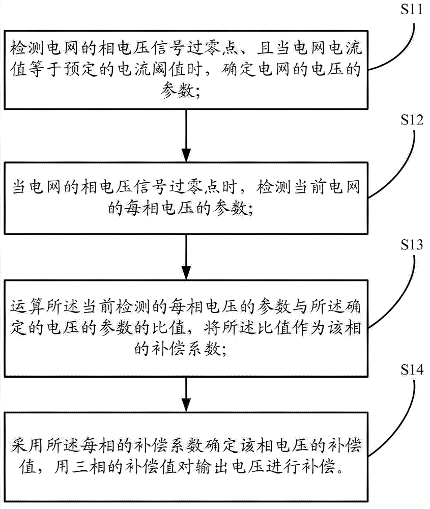
The invention discloses a dead zone compensating method which comprises the following steps of detecting the phase voltage signal zero crossing point of a power grid, and when the current value of the power grid is equal to a preset current threshold, determining the voltage parameter of the power grid; during the phase voltage signal zero crossing point of the power grid, detecting the parameter of each phase voltage of the current power grid; calculating the ratio of the currently detected parameter of each phase voltage to the determined voltage parameter of the power grid, and taking the ratio as a compensating factor of the phase; determining the compensation value of each phase voltage by adopting the compensating factor of each phase, and compensating an output voltage by utilizing the compensation values of three phases. By adopting the compensating method disclosed by the invention, the compensation effect is better than that of the prior art; after compensation, the content of current harmonics is reduced, the voltage is stable, and the current fluctuation is small.

Description

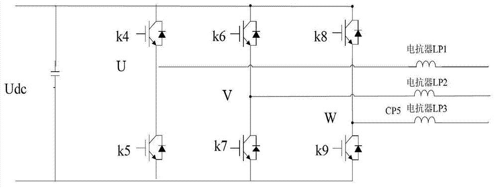
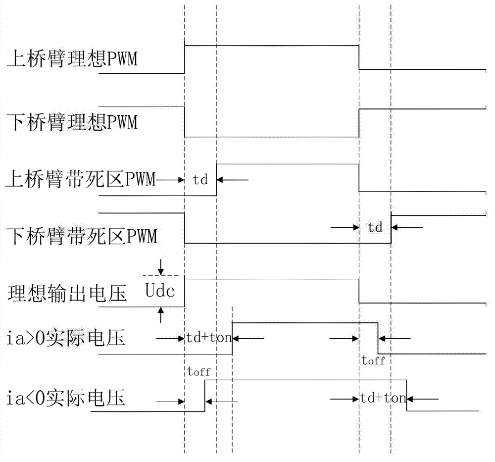
technical field [0001] The invention relates to the field of power control, in particular to a dead zone compensation method. Background technique [0002] In the prior art, electric devices including power switches, such as frequency converters or inverters, control the switching on or off of the switching tubes during the working process. During the turn-on or turn-off process, there will be a dead time, which will lead to the problem of output voltage distortion. The following is an example of a three-phase photovoltaic grid-connected inverter. [0003] see figure 1 The electrical schematic diagram of the three-phase photovoltaic grid-connected inverter in , the upper and lower switching devices of the same bridge arm work in a complementary state. The three-phase photovoltaic grid-connected inverter adopts a three-phase full-bridge topology. K4 and k5 form the same bridge arm. Similarly, K6, k7, and K8 and k9 form a bridge arm respectively. Because various switching d...

Claims


Application Information

Patent Timeline
Patent Type & Authority Applications(China)
IPC IPC(8): H02M7/48
Inventor 刘志强张东升苏位峰卫三民苟锐锋李侠周京华章小卫
Owner CHINA XD ELECTRIC CO LTD
Learn More