Lighting apparatus
A technology for lighting equipment and light source units, applied in lighting and heating equipment, lighting devices, components of lighting devices, etc., can solve the problem of inability to assemble lighting equipment with a large light-emitting area, inability to arrange light-emitting panels, and damage the advantages of planar light-emitting panels And other issues
- Summary
- Abstract
- Description
- Claims
- Application Information
AI Technical Summary
Problems solved by technology
Method used
Image
Examples
no. 1 example
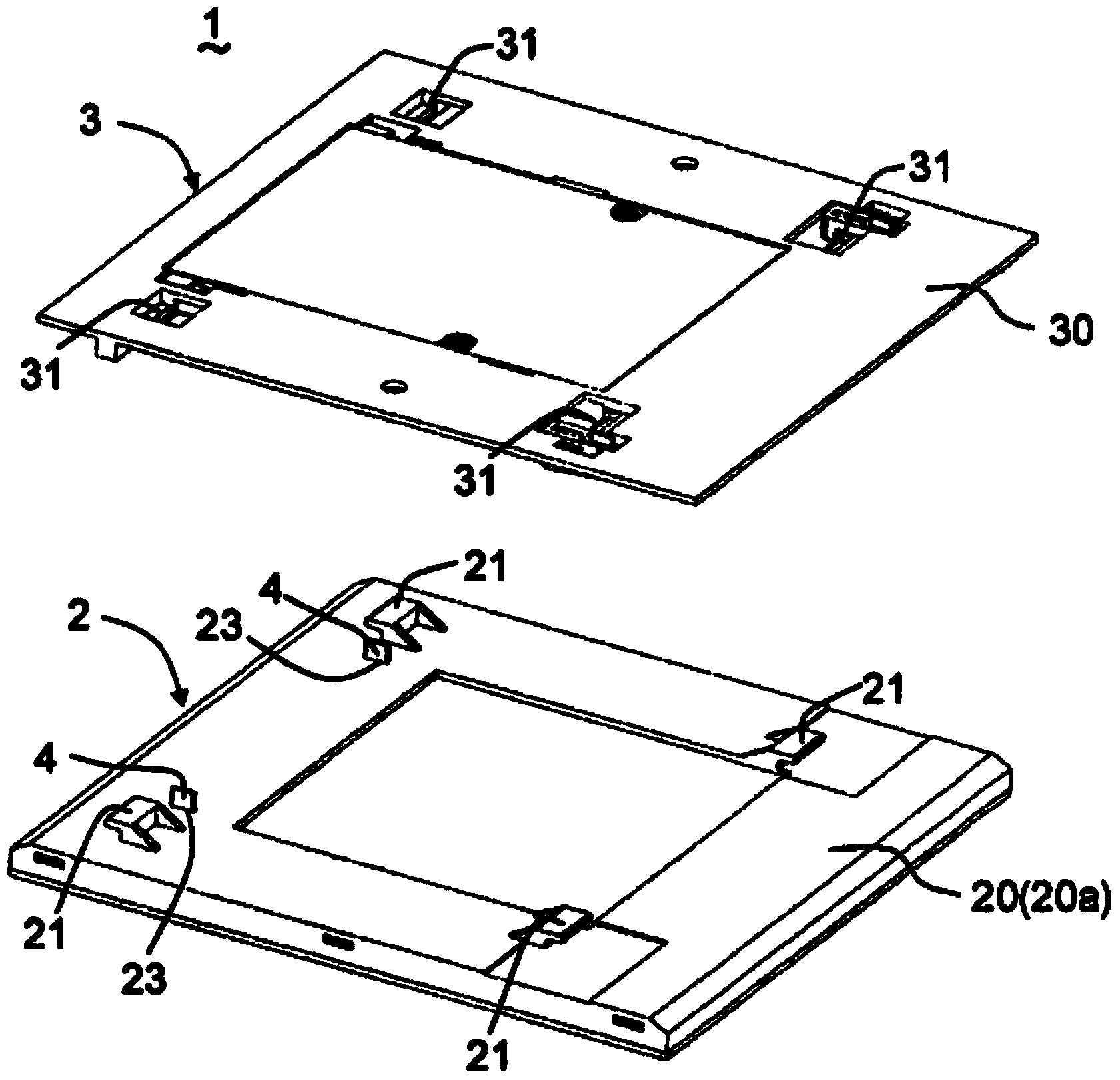
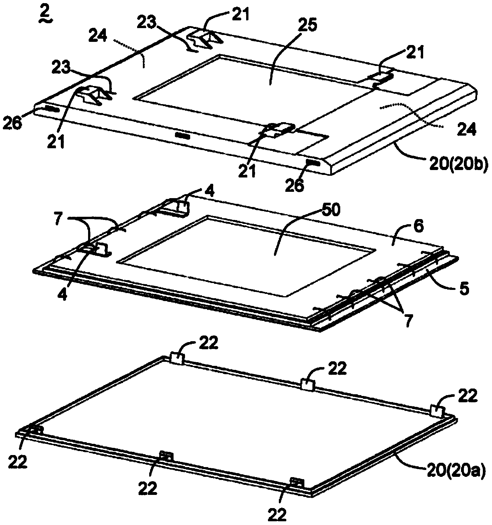
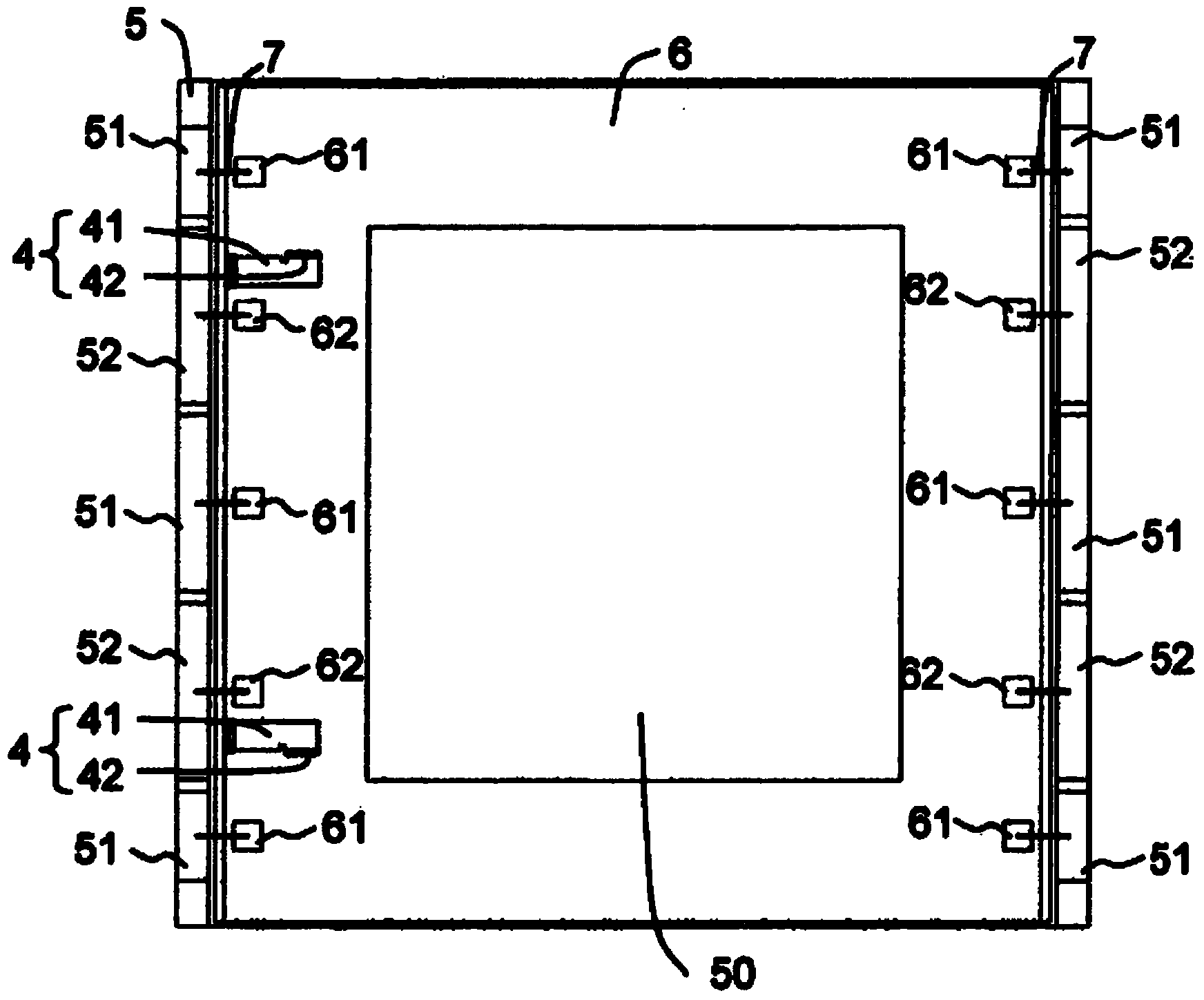
[0039] refer to Figure 1 to Figure 6 A lighting device according to an embodiment of the present invention will be described. Such as Figure 1 to Figure 6 As shown in , the lighting device 1 of this embodiment includes: a light source unit 2 having a box 20 for accommodating a planar light-emitting panel 5 using an organic EL element; The housing 30 of the lit (printed) circuit board 8 . exist figure 1 In the example of the present invention, the case 30 is a board frame, and the circuit board 8 is held in the board frame 30 . The (printed) wiring board 6 is housed in the case 20 of the light source unit 2 together with the light emitting board 5 . For the light source unit 2, a plurality (2) of claws 21 adapted to be engaged with the installation unit 3 are provided on the surface opposite to the installation unit 3 (its back side), and a plurality of (two) claws 21 for connecting the wiring board 6 to the installation unit 3 are provided. A plurality (two) of terminal...
no. 2 example
[0060] In the lighting device described in Document 2, the concave portion overlaps a part of the light emitting surface of the light emitting panel, which causes a non-light emitting region (a region that does not emit light) on the light emitting surface. As a result, for example, in the case of arranging the light-emitting panels side by side, since no light is emitted in the concave portion, a lighting device having a large light-emitting surface cannot be assembled. Furthermore, in the lighting fixture described in Document 3, a part of the housing overlaps a part of the light emitting surface of the light emitting panel, which also causes a non-light emitting area. In such a lighting device, the facilitation of installation of the light emitting panel causes unstable holding of the light emitting panel, and holding the light emitting panel firmly may make installation and detachment difficult.
[0061] The second embodiment is a lighting device configured to be able to e...
no. 3 example
[0088] refer to Figure 13 A and 13B illustrate a lighting device according to a third embodiment of the present invention. In the lighting apparatus 1 of the present embodiment, each engaging portion 21a of the light source unit 2 includes a U-shaped hook piece, and each engaged portion 31a of the mounting unit 3 constitutes a shaft member. That is, the U-shaped engaging portion 21a is hung on the shaft-shaped engaged portion 31a, whereby the light source unit 2 can freely rotate relative to the mounting unit 3 around the rotation axis of the engaged portion 31a. In this example, the engaging portions 21 a are arranged at both ends of one side of the light source unit 2 , and the engaged portions 31 a are arranged at both ends of one side of the mounting unit 3 . The holding portion 21b is arranged on the opposite side to the side on which the engagement portion 21a is arranged, and the held portion 31b is arranged on the opposite side to the side on which the engaged portio...
PUM
 Abstract
Description
Claims
Application Information
 - R&D
- Intellectual Property
- Life Sciences
- Materials
- Tech Scout
- Unparalleled Data Quality
- Higher Quality Content
- 60% Fewer Hallucinations
Browse by: Latest US Patents, China's latest patents, Technical Efficacy Thesaurus, Application Domain, Technology Topic, Popular Technical Reports.
© 2025 PatSnap. All rights reserved.Legal|Privacy policy|Modern Slavery Act Transparency Statement|Sitemap|About US| Contact US: help@patsnap.com


