Injection mold device

An injection mold and corresponding position technology, which is applied in the field of injection molding equipment, can solve the problems of reducing injection molding precision, inconvenient mold opening, and unfavorable production efficiency of enterprises, so as to achieve the effect of improving injection molding precision, increasing production efficiency, and reducing reprocessing

Inactive Publication Date: 2013-11-27
成都万顺达模具零件有限公司
View PDF0 Cites 4 Cited by
  • Summary
  • Abstract
  • Description
  • Claims
  • Application Information

AI Technical Summary

Problems solved by technology

[0004] Aiming at the above problems that the plastic products with complex shapes are often inconvenient to open the movable mold and the fixed mold, the injection molding cannot be completed in one step, and the injection molding precision can only be reduced, and the shape requirements can be achieved through post-processing, which is not conducive to the production efficiency of the enterprise. An injection molding device is provided

Method used


Image

  • Injection mold device

Examples


Embodiment 1

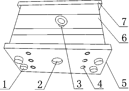
[0022] Such as figure 1 As shown, a kind of injection mold device comprises front baffle 5, a plurality of cavity plates 6 and rear baffle 7 with cavities inside, and a plurality of said cavity plates 6 are located at front baffle 5 and rear baffle. Between the plates 7, and a plurality of the cavity plates 6 are arranged sequentially, the sides of the adjacent two cavity plates 6, the front baffle plate 5 and the cavity plate 6, the cavity plate 6 and the rear baffle plate 7 are mutually Fitting, the front baffle 5 is also provided with an injection hole 2, and the rear baffle 7 is also provided with an exhaust hole.

[0023] The set front baffle 5, multiple cavity plates 6 and rear baffle 7 are combined to form the cavity of the injection mold, and the cavity part is composed of front baffle 5, multiple cavity plates 6 and rear baffle 7. Composition, this structure allows the cavity of the above structure to be set into a more complex structure, that is, at the structure wh...

Embodiment 2

[0025] This embodiment is further improved on the basis of embodiment 1, as figure 1 As shown, at least two through holes are provided at corresponding positions on the front baffle plate 5, a plurality of cavity plates 6 and the rear baffle plate 7, and at least two guide posts 1 are also included, each of the guide posts 1 and the through hole in the corresponding position form a clearance fit.

[0026] The provided through holes and the guide column 1 facilitate positioning when the front baffle 5 , multiple cavity plates 6 and the rear baffle 7 are connected.

[0027] It also includes lifting lugs 3 which are fixedly connected to the cavity plate 6 .

[0028] The set lug 3 facilitates the convenience of moving the present invention.

[0029] The two adjacent cavity plates 6, the front baffle plate 5 and the cavity plate 6, the cavity plate 6 and the rear baffle plate 7 are all provided with bolt holes, and also include connecting bolts 4. The cavity plate 6, the front b...


PUM


Abstract

The invention discloses an injection mold device which comprises a front baffle (5), a plurality of cavity plates (6) with cavities on the inner sides, and a rear baffle (7), wherein the cavity plates (6) are positioned between the front baffle (5) and the rear baffle (7), and are arranged in sequence; the side surfaces of the two adjacent cavity plates, the side surfaces of the front baffle and one cavity plate (6) as well as the side surface of another cavity plate (6) and the rear baffle (7) are attached to each other; an injection hole (2) is formed in the front baffle (5); an exhaust hole is formed in the rear baffle (7). Compared with the prior art, the cavity part of a mold cavity comprise a plurality of parts, the mold unloading is still smoothly completed after the cavity body of the mold cavity is arranged in a more complex shape, and the injection precision of plastic products of more complex shapes in the injection molding process is beneficial to improvement, so that the subsequent reprocessing is avoided or reduced, and the enterprises' production efficiency is beneficial to improvement.

Description

technical field [0001] The invention relates to the field of injection molding equipment, in particular to an injection mold device. Background technique [0002] Injection molding is a processing method used in the mass production of certain parts with complex shapes. Specifically, it refers to injecting heated and melted materials into a mold cavity under high pressure, and after cooling and solidifying, molded products are obtained. Injection mold is a tool for producing plastic products, which gives plastic products complete structure and precise dimensions. [0003] Existing injection mold is made up of two parts of movable mold and fixed mold, and movable mold and fixed mold are closed to form gating system and mold cavity during injection molding, and movable mold and fixed mold are separated so that take out plastic product when mold is opened. However, due to the ever-changing shapes and structures of plastic products, plastic products with complex shapes are often...

Claims


Application Information

Patent Timeline
Patent Type & Authority Applications(China)
IPC IPC(8): B29C45/26B29C45/34B29C45/66
Inventor 艾俊钟树军李强
Owner 成都万顺达模具零件有限公司
Why Eureka
Try Eureka