
Novel efficient notch airfoil shape of parafoil unmanned plane and optimum design method thereof

A notch and airfoil technology, applied in the field of parafoil UAV, can solve the problems of unfavorable lift-to-drag ratio, uneven aerodynamic load distribution, separation of the upper surface of the parafoil, etc., to achieve stable control of the angle of attack range and improve the efficiency of pitch control , the effect of large control angle of attack range

Active Publication Date: 2013-11-27
CHINA AEROSPACE TIMES ELECTRONICS CORP
View PDF3 Cites 2 Cited by
  • Summary
  • Abstract
  • Description
  • Claims
  • Application Information

AI Technical Summary

Problems solved by technology

[0005] (1) The position of the maximum camber is near the front, which is likely to cause uneven distribution of aerodynamic load along the chord direction, mainly concentrated near the front edge, causing uneven force on the parachute;
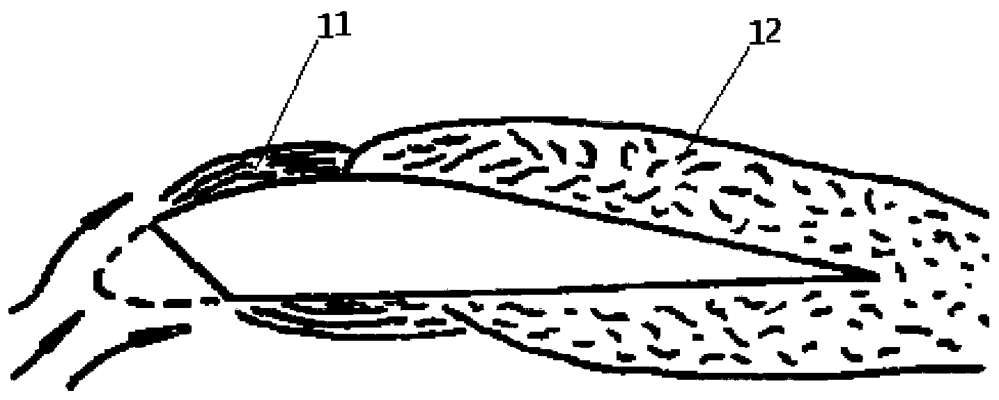
[0006] (2) The lower airfoil is straight, and the starting point of the leading edge notch is above the leading point of the chord line, which may easily cause the upper surface of the parafoil to separate prematurely, such as figure 1 shown;
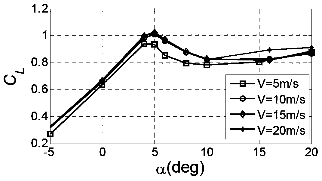
[0007] (3) The CLARK-Y notched airfoil stalls at a small angle of attack, and the stall angle of attack is about 5°, such as figure 2 As shown, it is not conducive to the use of the maximum lift-to-drag ratio, the aerodynamic efficiency is reduced, and the control of the pitch state of the ram parafoil is also limited.

Method used


Image

  • Novel efficient notch airfoil shape of parafoil unmanned plane and optimum design method thereof
  • Novel efficient notch airfoil shape of parafoil unmanned plane and optimum design method thereof
  • Novel efficient notch airfoil shape of parafoil unmanned plane and optimum design method thereof

Examples


Embodiment 1

[0042] as attached Image 6 As shown, the slit airfoil of the present invention is connected to the fuselage of the drone through the parachute rope 2, and is connected to the steering gear on the fuselage through the trailing edge control rope 3. When inflated, the airflow enters and exits the air chamber 5 of the parafoil through the cutout 1 at the leading edge, so that the canopy 4 takes on an airfoil shape and maintains the inflation stiffness. Manipulate the rope to realize the control of α.

Embodiment 2

[0044] The CFD method is used to analyze the aerodynamic characteristics of the slit airfoil of the present invention after inflation. When the Reynolds number Re=0.66e+06, the lift characteristics and the lift-to-drag ratio characteristics are shown in the appendix Figure 7 , when the installation angle α=6°-8°, it has the maximum lift-to-drag ratio, and the present invention has a stable pitch control range within the installation angle α=0°-12°. Among them, when the installation angle α=6°, the flow characteristics are shown in the attached Figure 8 , the pressure distribution of the notched airfoil see the attached Figure 9 .

[0045] Among them, the Reynolds number Re is the ratio of the fluid inertial force to the viscous force, ρVl / μ, where V is the flow velocity, l is the length of the flowing object, ρ is the density, and μ is the fluid viscosity coefficient. The characteristics of the airfoil are greatly affected by the Reynolds number during its motion, which a...


PUM


Abstract

The invention provides a notch airfoil shape of a stamping parafoil and an optimum design method thereof. The optimum design method comprises the following steps of selecting a high aerodynamic efficiency base airfoil shape, designing a front edge notch and designing front edge notch parameter optimization. Compared with a conventional traditional CLARK-Y notch airfoil shape, the notch airfoil shape has the advantages that the max thickness of the notch airfoil shape is large, the thickness distribution is uniform, the space of a parafoil air chamber is large, and the notch airfoil shape is beneficial to improving of the charge efficiency and the charge rigidity of the parafoil; as the distribution of surface pressure along a thread direction is uniform, the notch airfoil shape is beneficial to arrangement of a parafoil parachute cord, and the pitching driving efficiency is improved; the stalling angle is large, the usable aerodynamic efficiency is high, and the notch airfoil shape has the large stalling angle range for smooth and stable control.

Description

technical field [0001] The invention relates to a stamped parafoil profile for a parafoil drone, in particular to a notched airfoil for a parafoil drone. In addition to being applicable to parafoil drones, the present invention is also applicable to the design and manufacture of other stamping parafoils. Background technique [0002] The parafoil UAV technology is a new type of UAV formed by using a stamped parafoil to replace the traditional wing to provide lift for the parafoil UAV. The stamped parafoil is limited by the plane shape and the characteristics of the parafoil, and cannot be optimized for aerodynamic parameters like the traditional fixed wing. Therefore, the optimized design of the notched airfoil becomes the key to improving the aerodynamic performance of the parafoil UAV. The efficiency and efficiency are decisive factors for the performance of the ram parafoil, and directly affect the parachute opening of the ram parafoil and the flight performance of the p...

Claims


Application Information

Patent Timeline
Patent Type & Authority Applications(China)
IPC IPC(8): B64C31/036
Inventor 龚翠翠司亮马祥森陈建国
Owner CHINA AEROSPACE TIMES ELECTRONICS CORP
Learn More