
Double-layer bridge floor cable-stayed bridge

A cable-stayed bridge and double-layer technology, applied in the direction of cable-stayed bridges, bridges, bridge parts, etc., can solve the problems of large main girder structure height, affecting the traffic safety of the upper bridge deck, poor ventilation, etc., and achieve a small structure height , good visibility and permeability, and the effect of wind load effect is small

Active Publication Date: 2013-11-27
GUANGZHOU MUNICIPAL ENG DESIGN & RES INST CO LTD
View PDF4 Cites 5 Cited by
  • Summary
  • Abstract
  • Description
  • Claims
  • Application Information

AI Technical Summary

Problems solved by technology

However, the traditional double-deck cable-stayed bridge has the following problems in practical application: in terms of traffic safety, if the traffic accident on the lower deck may damage or destroy the load-bearing structure, thereby affecting the traffic safety of the upper deck; In terms of performance, for the case of box-shaped girders, the ventilation of the lower deck is not good, and problems such as vehicle exhaust and noise have a greater impact on the traffic comfort of the lower deck; in terms of structural stability, due to the traditional double-deck For cable-stayed bridges, the upper and lower girders are integrated, the height of the girder structure is large, and the wind load effect has a greater impact on the structure, so that the wind resistance stability of the structure has a certain negative impact

Method used


Image

  • Double-layer bridge floor cable-stayed bridge
  • Double-layer bridge floor cable-stayed bridge

Examples


Embodiment Construction

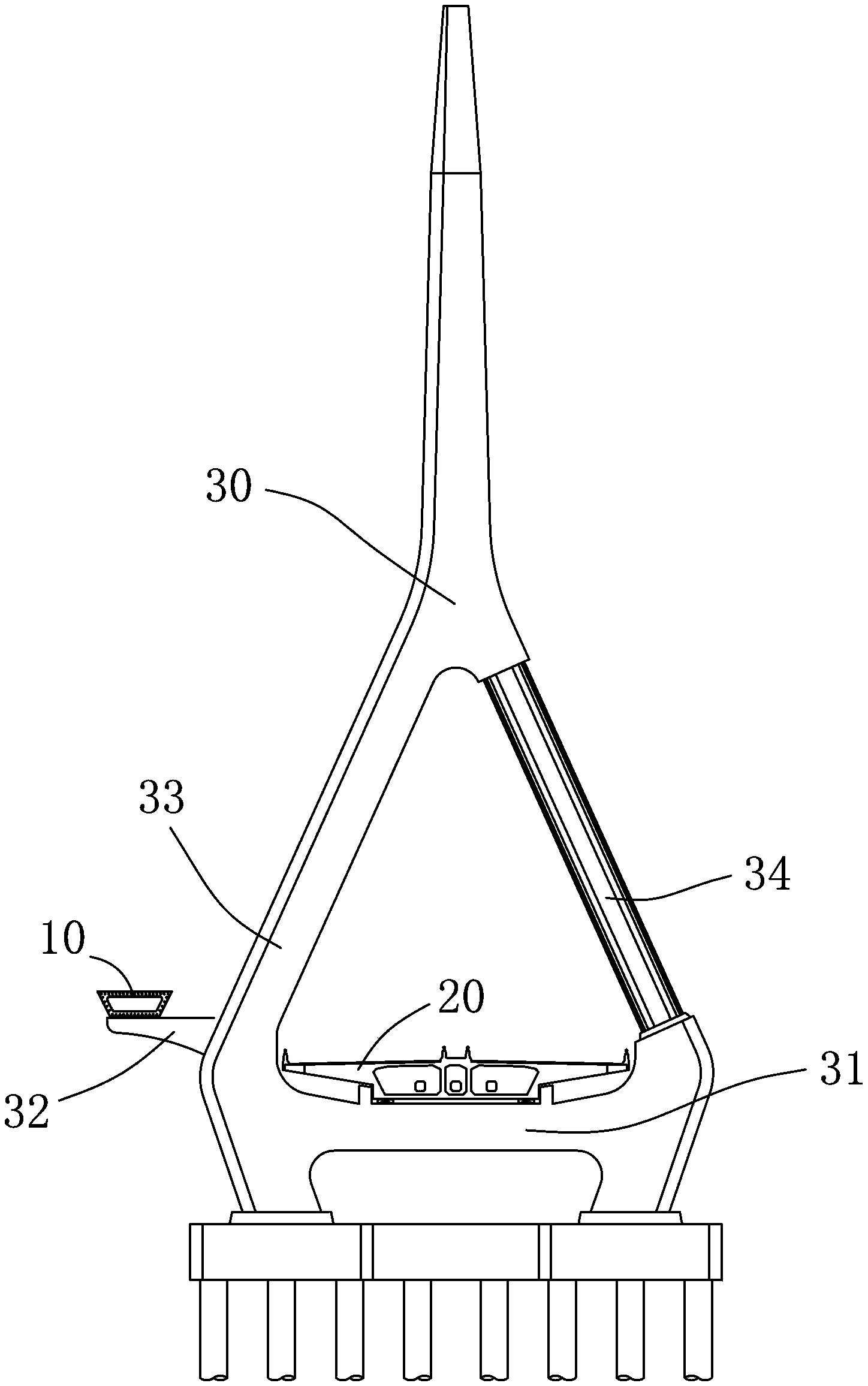
[0012] refer to figure 1 and figure 2 , a double-deck cable-stayed bridge of the present invention comprises an inverted Y-shaped pylon 30, an upper floor girder 10 and a lower floor main girder 20 that are independent of each other on the inverted Y-shaped pylon 30, and an inverted Y-shaped pylon 30 The lower bridge pylon beam 31 is set in the middle of the bottom, and the inverted Y-shaped bridge tower 30 has an upper bridge tower beam 32 extending outward from the side edge higher than the lower bridge tower beam 31. The tower 30 is connected and arranged on the lower bridge tower beam 31 , and the upper main girder 10 is connected with the inverted Y-shaped bridge tower 30 and arranged on the upper bridge tower beam 32 through stay cables.

[0013] The upper main girder 10 and the lower main girder 20 in this double-deck cable-stayed bridge are completely separated, the upper main girder 10 is placed above the lower main girder 20 side through the upper bridge pylon beam...


PUM


Abstract

The invention discloses a double-layer bridge floor cable-stayed bridge. The double-layer bridge floor cable-stayed bridge comprises a reverse-Y-shaped bridge tower, an upper layer main girder and a lower layer main girder, wherein the upper layer main girder and the lower layer main girder are arranged on the reverse-Y-shaped bridge tower and are independent from each other. A lower bridge tower beam is arranged in the middle below the reverse-Y-shaped bridge tower, and the edge on one side, higher than the lower bridge tower beam, of the reverse-Y-shaped tower extends outwards to form an upper bridge tower beam. The upper layer main girder and the lower layer main girder are respectively connected with the reverse-Y-shaped bridge tower through stay cables. The upper layer main girder is placed above one side of the lower main girder through the upper bridge tower beam. The upper layer main girder and the lower layer main girder are respectively connected with the reverse-Y-shaped bridge tower through the stay cables. The projection, on a horizontal plane, of the upper layer main girder and the projection, on the horizontal plane, of the lower layer main girder are independent from each other, so that the upper layer main girder does not affect the space area on the lower layer main girder, and a vehicular bridge composed of the lower layer main girder has good view permeability performance. Meanwhile, the upper layer main girder and the lower layer main girder are separated, the structure height of the main girders is small, and the wind load effect is small. The double-layer bridge floor cable-stayed bridge is used in the technical field of bridge engineering.

Description

technical field [0001] The invention relates to the technical field of bridge engineering, in particular to a double-layer cable-stayed bridge. Background technique [0002] The projections of the upper and lower decks on the horizontal plane of traditional double-deck cable-stayed bridges overlap each other and the upper and lower decks are structurally integrated. The main structural systems are the following two, one is the cable system Structural system combined with trusses: steel trusses or composite trusses are used as load-bearing members and the upper and lower chords are used to form a double-layer bridge deck. The second is the structural system combined with cable system and box girder: for long-span cable system bridges, the main girder can use a wide and flat multi-chamber box girder section as the load-bearing member and use the top and bottom of the box girder to form a double layer bridge deck. However, the traditional double-deck cable-stayed bridge has ...

Claims


Application Information

Patent Timeline
IPC IPC(8): E01D11/04E01D19/00
Inventor 宁平华熊洪波杨勇郭建民魏立新乐小刚胡会勇谭礼陵刘兵
Owner GUANGZHOU MUNICIPAL ENG DESIGN & RES INST CO LTD
Learn More