Method for calculating electric field probe rotation offset through circular polarization antenna axial ratio directional diagram

A circularly polarized antenna and directional pattern technology, applied in the direction of the antenna radiation pattern, the use of electrical devices, the use of electromagnetic means, etc., can solve the problem of heavy workload, no automatic compensation circularly polarized antenna, and electric field probes that cannot be rotated, etc. problem, to achieve the effect of small rotation angle and reduced workload

Inactive Publication Date: 2013-11-27
NAT SPACE SCI CENT CAS
View PDF3 Cites 15 Cited by
  • Summary
  • Abstract
  • Description
  • Claims
  • Application Information

AI Technical Summary

Problems solved by technology

[0008] This method can obtain accurate values ​​of Δx and Δy offsets without installing heavy optical measurement equipment, but the main problems are: 1) Four near-field measurement tasks need to be completed, and the workload is huge; 2) Some electric field probes It cannot achieve rotation within 360°; 3) It does not have the ability to automatically compensate for circularly polarized antenna Δx and Δy offsets

Method used


Image

  • Method for calculating electric field probe rotation offset through circular polarization antenna axial ratio directional diagram
  • Method for calculating electric field probe rotation offset through circular polarization antenna axial ratio directional diagram
  • Method for calculating electric field probe rotation offset through circular polarization antenna axial ratio directional diagram

Examples


Embodiment Construction

[0071] The present invention will be further described below in conjunction with the accompanying drawings and specific embodiments, and realized through the following technical solutions.

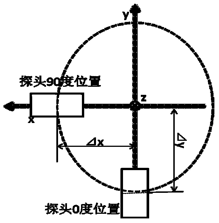
[0072] In order to describe in detail the method for calculating the rotation offset of the electric field probe using the axial ratio pattern of the circularly polarized antenna of the present invention, first,

[0073] According to Kerns' plane wave coupling matrix theory, the relationship between the probe response and the spectral function of the antenna under test is obtained:

[0074] b 0 ′ ( x , y , d ) = a 0 F ′ ∫ ∫ t 10 ‾ ( K ...


PUM


Abstract

The invention relates to a method for calculating electric field probe rotation offset through a circular polarization antenna axial ratio directional diagram. According to the method, the nonlinearity least square method is used for guiding out a mathematic model of the relation between the offset after electric field probe rotation and the circular polarization antenna axial ratio directional diagram, the Gauss-Newton iterative method is used for carrying out numerical solution on the offset after electric field probe rotation to obtain electric field probe rotation offset delta x and delta y for compensation for near-far field conversion, and therefore an accurate circular polarization antenna far field directional diagram and the accurate axial ratio directional diagram are obtained. According to the method, the accurate value of the delta x and the delta y of electric field probe rotation offset can be obtained without arranging heavy optical measurement equipment in an erecting mode, only two times of plane near field measurement is needed, and the workload is reduced. An electric field probe used for measurement just needs to be rotated by 90 degrees instead of being rotated by 360 degrees, and electric field probe rotation offset can be automatically compensated.

Description

technical field [0001] The invention relates to the technical field of antenna near-field measurement, in particular to a method for calculating the rotation offset of an electric field probe by using a circularly polarized antenna axial ratio pattern. Background technique [0002] Antenna near-field measurement technology is a high-precision antenna measurement and diagnosis technology widely used at home and abroad. The near-field of the antenna is usually divided into a near-field induction area and a near-field radiation area. The near-field induction area is also called the reactance near area and the energy storage area. The far-field pattern of the antenna can be calculated. When the area away from the antenna to be tested is 3 wavelengths away from the near-field radiation area, the influence of the induced near-field on the antenna measurement can be ignored at this time. In the near-field radiation area, the electric field, magnetic field, and propagation directi...

Claims


Application Information

Patent Timeline
Patent Type & Authority Applications(China)
IPC IPC(8): G01B7/14G01R29/10
Inventor 易敏王宏建刘广陈雪赵鑫
Owner NAT SPACE SCI CENT CAS
Why Eureka
Try Eureka