Switchover imaging photographic device and method

A technology for switching imaging and photographing devices, applied in the field of optical imaging, can solve the problems of inability to achieve aerial photography, low frame rate, reducing the imaging resolution of aerial photography cameras, etc. Reduce costs and technical requirements, and ensure the effect of normal use

Active Publication Date: 2015-07-08
BEIJING RES INST OF SPATIAL MECHANICAL & ELECTRICAL TECH
View PDF5 Cites 0 Cited by
  • Summary
  • Abstract
  • Description
  • Claims
  • Application Information

AI Technical Summary

Problems solved by technology

[0003] At present, the following two problems exist in the process of transforming aerial photography cameras: 1. The existing digital photosensitive device does not have a photosensitive area of ​​80mm×80mm or larger at one time, and the photosensitive device with a larger area has a higher frame rate. The lower it is, the less it can meet the needs of aerial photography
2. Carry out digital transformation of sensors in existing aerial photographic cameras, whether it is the seamless splicing technology of multiple CCD or CMOS sensors, or the method of shrinking imaging photography splicing (as disclosed on October 24, 2007, the patent publication number is CN101059598A , a Chinese patent titled a secondary imaging photography method and device), which cannot completely cover the imaging area of ​​the original aerial photography camera, or do not reduce the imaging resolution of the original aerial photography camera
This makes a truly effective digital transformation of aerial photography cameras impossible

Method used


Image

  • Switchover imaging photographic device and method
  • Switchover imaging photographic device and method

Examples


Embodiment

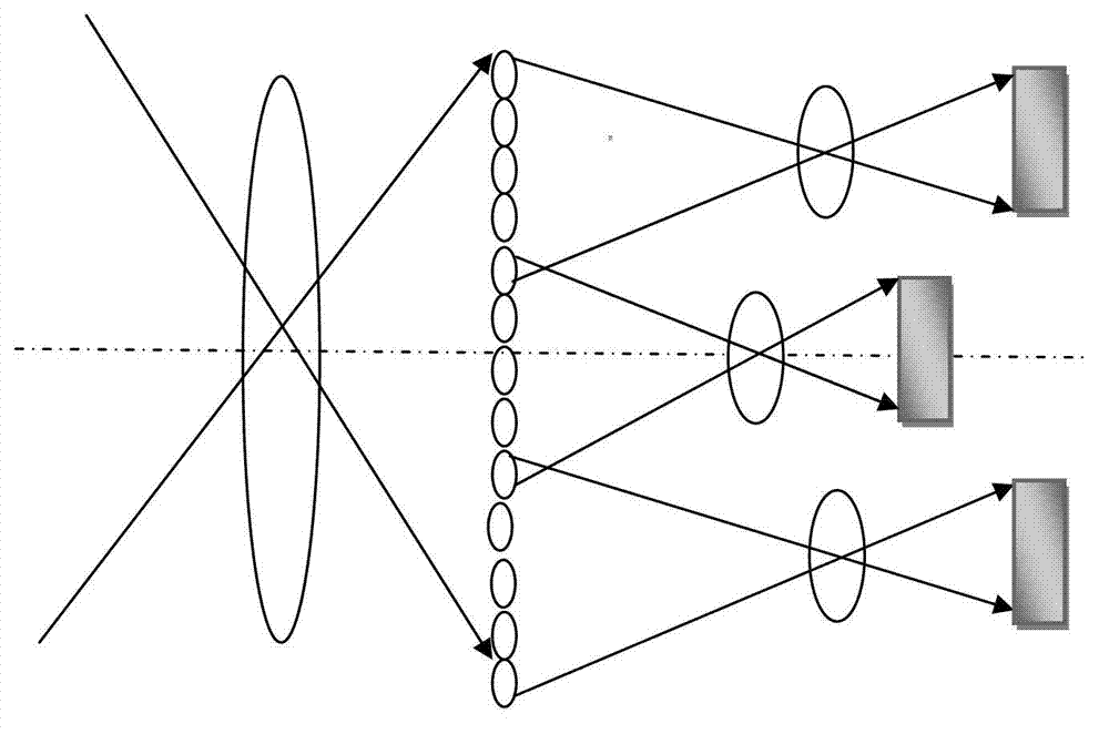
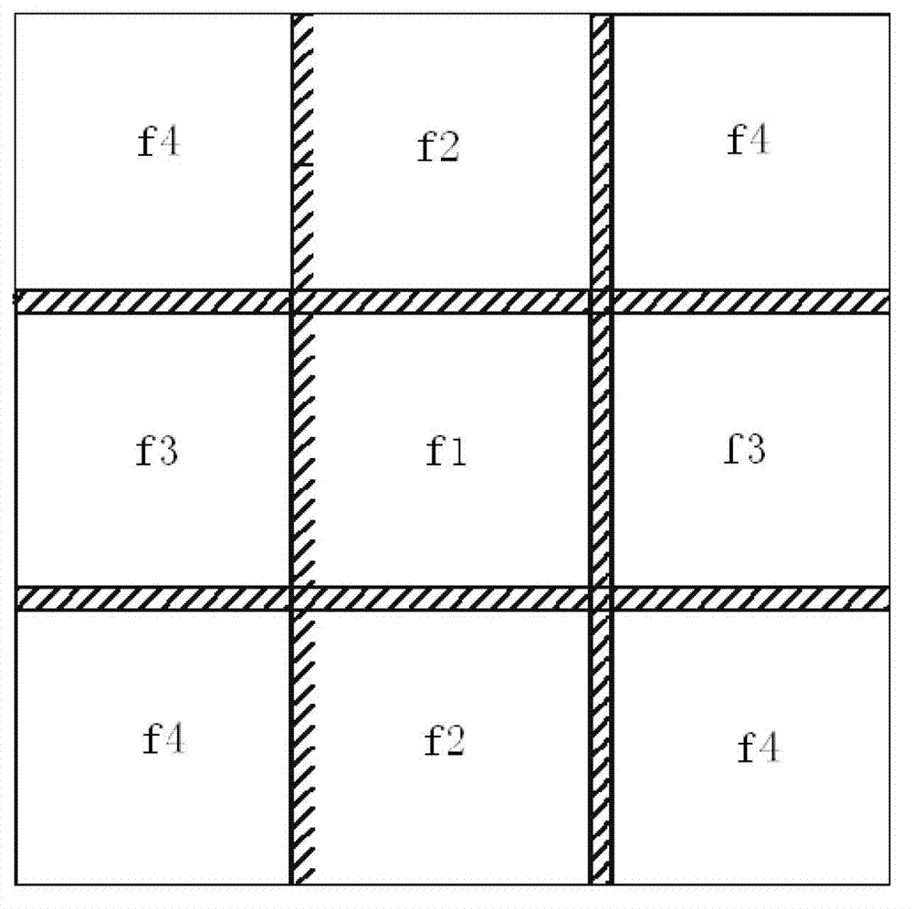
[0030] The description will be made by taking the number of relay imaging photography lenses as 3×3 (when m=3, n=3) as an example.

[0031] Such as figure 1 As shown, the present invention is a method of combining a plurality of relay imaging photography systems with different focal lengths. Each relay imaging photography system is composed of a relay imaging photography lens and corresponding photosensitive area array devices such as CCD and CMOS. The focal plane image of the imaging photography system is imaged on the corresponding photosensitive array CCD or CMOS and other devices through the conversion imaging photography lens. Different focal length transfer imaging photography lenses perform transfer imaging on the focal plane of the imaging photography system. Every two adjacent transfer imaging photography lenses are not in the same plane, and each area array CCD or CMOS and other devices are unobstructed to ensure transfer imaging. The resolution of the photographic ...


PUM


Abstract

The invention relates to a switchover imaging photographic device which comprises an imaging photographic system which does not comprise light sensing devices, a micro lens array, switchover imaging photographic lenses and light sensing devices. The micro lens array is arranged on an imaging position of the imaging photographic system and fully covers an image plane of the imaging photographic system. Multiple sets of switchover imaging photographic lenses with different focal distances are arranged behind the micro lens array according to the principle that the focal distances of adjacent lenses are different and emitting light rays of the micro lens array are fully covered. The switchover imaging photographic lenses image the image plane of the imaging photographic system on the light sensing devices after the image plane is kept equal or amplified according to the geometry conjugation relationship. Each switchover imaging photographic lens corresponds to a light sensing device. Image stacking zones of all the light sensing devices are spliced and compounded to be an integral image. With the imaging photographic system, the micro lens array, the switchover imaging photographic lenses and the light sensing devices are combined to obtain an image which has equal or higher image quality and resolution and high geometric precision and a large complete image.

Description

technical field [0001] The invention belongs to the technical field of optical imaging, and relates to a device for switching imaging and photographing a system image plane by using the principle of optical object imaging to ensure that the original resolution remains unchanged or achieve a higher resolution. Background technique [0002] Currently widely used high-resolution aerial photography cameras all use film as the photosensitive device. The photosensitive area of ​​the film is large and the sensitivity is high, which is unmatched by digital cameras. However, due to the strong functionality and effectiveness of digital camera systems, image analysis and real-time transmission of captured images can be performed, which is the development trend of high-resolution aerial photography cameras today. Therefore, in order to achieve the effectiveness of large-format image shooting and use the original aerial photography equipment, it needs to be digitally transformed. [000...

Claims


Application Information

Patent Timeline
Patent Type & Authority Patents(China)
IPC IPC(8): G02B13/00H04N5/225
Inventor 葛婧菁张声荣林招荣朱大凯李福东曹桂丽刘玲陈皓朱建平
Owner BEIJING RES INST OF SPATIAL MECHANICAL & ELECTRICAL TECH
Why Eureka
Try Eureka