Permanent magnet motor magnetic steel installation and fixation retainer and permanent magnet motor magnetic cylinder comprising the same

A permanent magnet motor, fixed and maintained technology, applied to the rotating parts of the magnetic circuit, the shape/style/structure of the magnetic circuit, etc., can solve the problem of increasing the use of magnetic steel materials, being easily affected by high temperature or oil pollution, and long process time, etc. problems, to achieve the effect of improving production efficiency, simple and reasonable structure, and concise overall structure

Inactive Publication Date: 2013-11-27
WERNERFUJIAN POWER CO LTD
View PDF6 Cites 8 Cited by
  • Summary
  • Abstract
  • Description
  • Claims
  • Application Information

AI Technical Summary

Problems solved by technology

However, for the same bonding material, in the case of different bonding processes, the degree of shear force resistance after bonding will also vary greatly, and some may even differ by several times, and its instability is very prominent. After a long time of use, it is easy to be affected by high temperature or oil pollution, and the adhesive will age, causing the magnetic steel to fall off
The existing motor rotor punching and magnetic steel connection device (Chinese Patent Publication No.: CN 201063465Y), which has a rotor punching, the motor shaft is installed in the center of the rotor punching, and the magnetic steel is connected around the rotor punching, which is characterized in that The magnetic steel groove is punched on the rotor punching sheet, and the magnetic steel is inserted into the magnetic steel groove of the rotor punching sheet. By making the magnetic steel groove, the magnetic steel is inserted and fixed in the magnetic steel groove, but the cost is high, the process time is long, and the design It is necessary to keep a large air gap, which reduces the efficiency of the motor and increases the amount of magnetic steel material used, and after a period of use, it will still fall off

Method used


Image

  • Permanent magnet motor magnetic steel installation and fixation retainer and permanent magnet motor magnetic cylinder comprising the same
  • Permanent magnet motor magnetic steel installation and fixation retainer and permanent magnet motor magnetic cylinder comprising the same
  • Permanent magnet motor magnetic steel installation and fixation retainer and permanent magnet motor magnetic cylinder comprising the same

Examples


Embodiment Construction

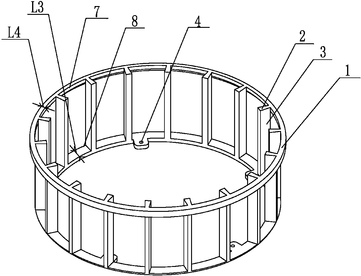
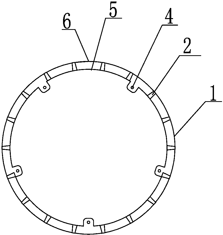
[0023] Such as Figure 1 to Figure 4 As shown, a permanent magnet motor magnetic steel installation and fixed cage, which includes a cylindrical cage-shaped cage body 1, the cage body 1 is provided with magnetic isolation strips 2 according to circular arcs, adjacent magnetic isolation strips 2 and the cage The space enclosed between the main body 1 is the magnetic isolation strip groove 3, and the opening of the magnetic isolation strip groove 3 is set such that the diameter L1 of the inner opening 5 is small, and the diameter L2 of the outer opening 6 is large.

[0024] Since the opening of the magnetic isolation strip slot 3 is set to have a small diameter L1 on the inner side and a large diameter L2 on the outer side, when the magnetic steel rotates, the magnetic isolation strips on both sides of the inner opening can produce a reaction force on the magnetic steel strip, which can effectively prevent the magnetic steel The strip is loose. The magnetic steel strip can be r...


PUM


Abstract

The invention discloses a permanent magnet motor magnetic steel installation and fixation retainer. The permanent magnet motor magnetic steel installation and fixation retainer is characterized by comprising a cylinder cage-shaped retainer body, wherein partition magnetic stripes are arranged on the retainer body according to equal arcs of a circumference, the space formed between adjacent partition magnetic stripes and the retainer body in an enclosing mode is a partition magnetic stripe groove, and openings of the partition magnetic stripe groove are arranged in the mode that the diameter of the opening on the inner side is smaller than the diameter of the opening on the outer side. By the adoption of the structure, reacting force generated by a trapezoid cross section can effectively prevent magnetic steel from getting loose, the magnetic steel can be fixedly connected with a magnetic yoke relatively with no need for an anaerobic adhesive, a stainless steel ring, a carbon fiber, a bolt lock and other materials, therefore, the installation process of the magnetic steel is greatly simplified, the installation efficiency is improved, the failure rate of a motor due to the fact that a magnetic steel strip falls off is reduced, and the production efficiency of the motor is improved. Moreover, the permanent magnet motor magnetic steel installation and fixation retainer can be manufactured in an injection molding mold opening mode, the mold opening cost is relatively low, the manufacturing is easy, and popularization and use are convenient.

Description

technical field [0001] The invention relates to a mounting and fixing cage for magnet steel in a motor, in particular to a magnet mounting and fixing cage for a permanent magnet motor, which belongs to a key part for magnet assembly of a permanent magnet motor. Background technique [0002] In a permanent magnet motor, the rotor poles are composed of several tile-shaped magnetic steel sheets, and are bonded to the outer circle of the rotor with high-strength glue. When the permanent magnet motor is working, its rotor rotates at a high speed, and the high-speed rotation of the rotor will generate a large centrifugal force. The magnetic steel that is not firmly bonded is easy to fall off, causing machine failure and reducing the service life of the motor. In order to solve this problem, people in the industry have also made a lot of efforts to design a variety of bonding materials with better bonding effects. However, for the same bonding material, in the case of different bo...

Claims


Application Information

Patent Timeline
Patent Type & Authority Applications(China)
IPC IPC(8): H02K1/28H02K1/27
Inventor 张雄峰
Owner WERNERFUJIAN POWER CO LTD
Why Eureka
Try Eureka