
United relay selection and power distribution method and system

A technology of power and relay nodes, applied in the field of cognitive radio, can solve problems such as large gap in calculation model, no consideration of relay nodes, and large interference of main users.

Active Publication Date: 2013-11-27
BEIJING UNIV OF POSTS & TELECOMM
View PDF2 Cites 23 Cited by
  • Summary
  • Abstract
  • Description
  • Claims
  • Application Information

AI Technical Summary

Problems solved by technology

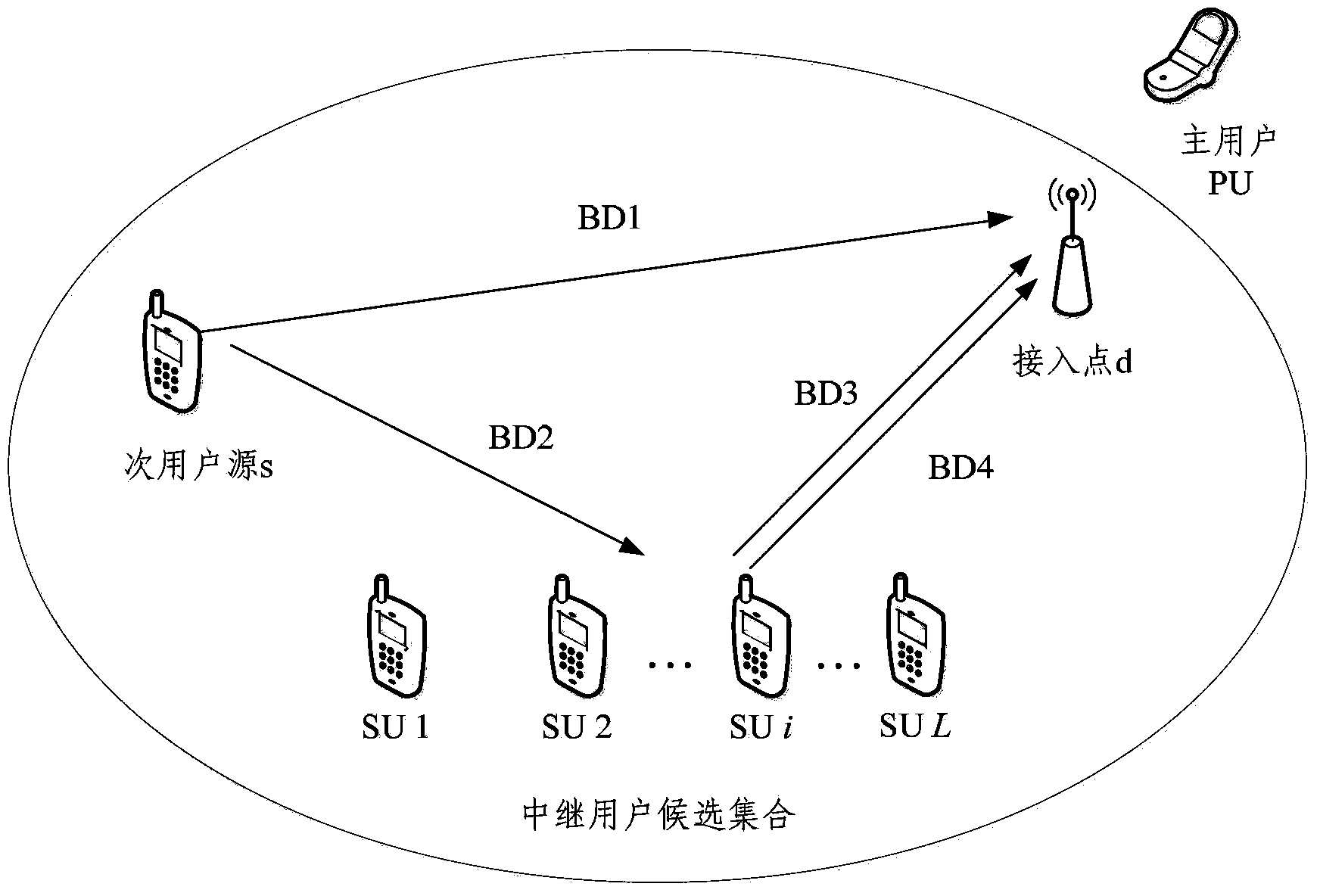
However, in the actual cognitive relay system, not only the performance of the source node, but also the performance of the relay node must be considered. The relay node not only forwards the data of the source node, but also transmits its own data, but in The existing technical solutions do not take into account the fact that the relay node also transmits its own data while forwarding the data of the source node, so the calculation model is far from the actual situation, and the interference to the primary user is also relatively large

Method used


Image

  • United relay selection and power distribution method and system
  • United relay selection and power distribution method and system
  • United relay selection and power distribution method and system

Examples


Embodiment 1

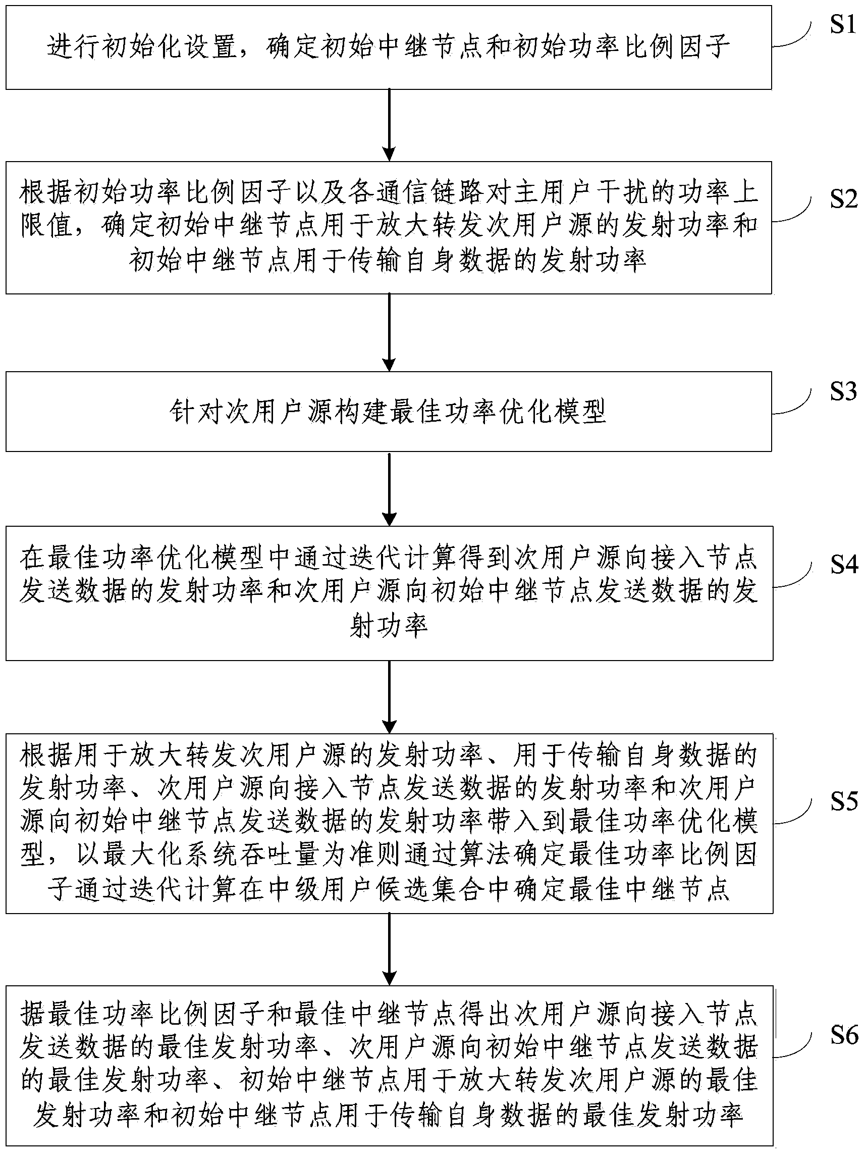
[0074] Embodiment 1 of the present invention provides a method for joint relay selection and power allocation, the steps of which are as follows figure 2 shown, including:

[0075] Step S1 , perform initialization settings, and determine an initial relay node and an initial power scaling factor θ, where 0≤θ≤1.

[0076] Step S2, according to the initial power scaling factor θ and the power upper limit value P of each communication link interfering with the primary user 0 , to determine the transmit power P used by the initial relay node to amplify and forward the secondary user source 3 and the transmit power P used by the initial relay node to transmit its own data 4 .

[0077] Step S3, constructing an optimal power optimization model for the secondary user source.

[0078] Step S4, obtain the transmission power P of the secondary user source to send data to the access node through iterative calculation in the optimal power optimization model 1 and the transmit power P o...

Embodiment 2

[0131] Embodiment 2 of the present invention also provides a system for joint relay selection and power allocation corresponding to the method in Embodiment 1. The composition diagram of the system is as follows Figure 4 shown, including:

[0132] Initialization setting unit 41 , determining relay node transmit power unit 42 , model building unit 43 , determining secondary user source transmit power unit 44 , optimal relay node determining unit 45 and optimal transmit power determining unit 46 .

[0133] The initialization setting unit 41 is used for performing initialization settings to determine an initial relay node and an initial power scaling factor θ, where 0≤θ≤1.

[0134] Determine the transmit power unit 42 of the relay node according to the initial power scaling factor θ and the upper limit value P of the power that each communication link interferes with the primary user 0 , to determine the transmit power P used by the initial relay node to amplify and forward the...


PUM


Abstract

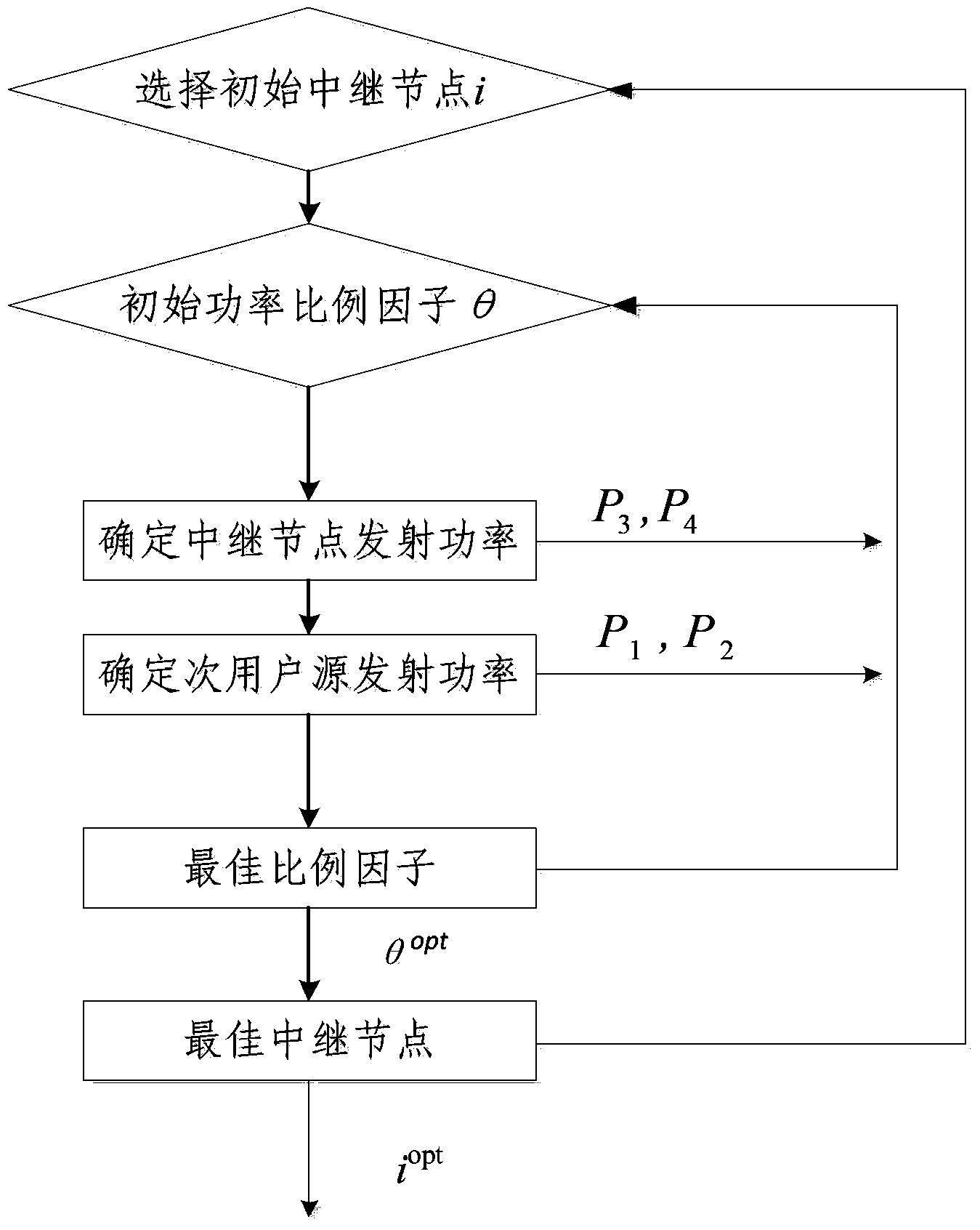
The invention discloses a united relay selection and power distribution method and system. The method comprises the steps that initialized setting is carried out, and initial relay nodes and initial power scaling factors are determined; according to the initial relay nodes, the initial power scaling factors and upper limit values of power interference from various channel links to a master user, transmitting emission power, used for magnifying and transmitting a secondary user source and for transmitting of the initial relay nodes, of the initial relay nodes is determined; in the optimal power optimization model, through iterative computation, emission power, for transmitting data to access nodes and the initial relay nodes, of the secondary user source is obtained; the optimal power scaling factor and the optimal relay node are determined through an algorithm. The fact that the relay nodes transmit the data of the secondary user source is considered, and meanwhile the data transmitted by the relay nodes are further considered; when a constraint condition of total emission power is met, interference to the master user is reduced, transmission performance of the relay nodes is guaranteed, and meanwhile system throughput is maximized.

Description

technical field [0001] The present invention relates to the field of cognitive radio technology, in particular to a method and system for joint relay selection and power allocation. Background technique [0002] With the development of broadband and intelligent mobile wireless communication, people have higher and higher requirements for the transmission rate of wireless communication, and the demand for wireless spectrum resources is also increasing sharply, which leads to the increasing scarcity of scarce spectrum resources and restricts The development of wireless communication technology. In order to solve the conflicting problems of spectrum utilization and spectrum resource shortage, the concept of cognitive radio was proposed, which allows the communication system to sense the surrounding communication environment and adaptively adjust system parameters according to changes in the environment to be more efficient, Perform dynamic spectrum access in a flexible manner ...

Claims


Application Information

Patent Timeline
Patent Type & Authority Applications(China)
IPC IPC(8): H04W72/08H04W72/54
CPCY02D30/70
Inventor 张英海余阳肖松松王朝炜王卫东王帅
Owner BEIJING UNIV OF POSTS & TELECOMM
Learn More