
Pneumatic vehicle tire

一种轮胎、车辆的技术,应用在特殊轮胎、车辆部件、轮胎零部件等方向,能够解决轮胎操纵性削弱等问题

Active Publication Date: 2013-11-27
CONTINENTAL REIFEN DEUTSCHLAND GMBH
View PDF5 Cites 3 Cited by
  • Summary
  • Abstract
  • Description
  • Claims
  • Application Information

AI Technical Summary

Problems solved by technology

However, with pneumatic vehicle tires having this tread base structure, it has been found that tire handling is impaired

Method used


Image

  • Pneumatic vehicle tire
  • Pneumatic vehicle tire
  • Pneumatic vehicle tire

Examples


Embodiment Construction

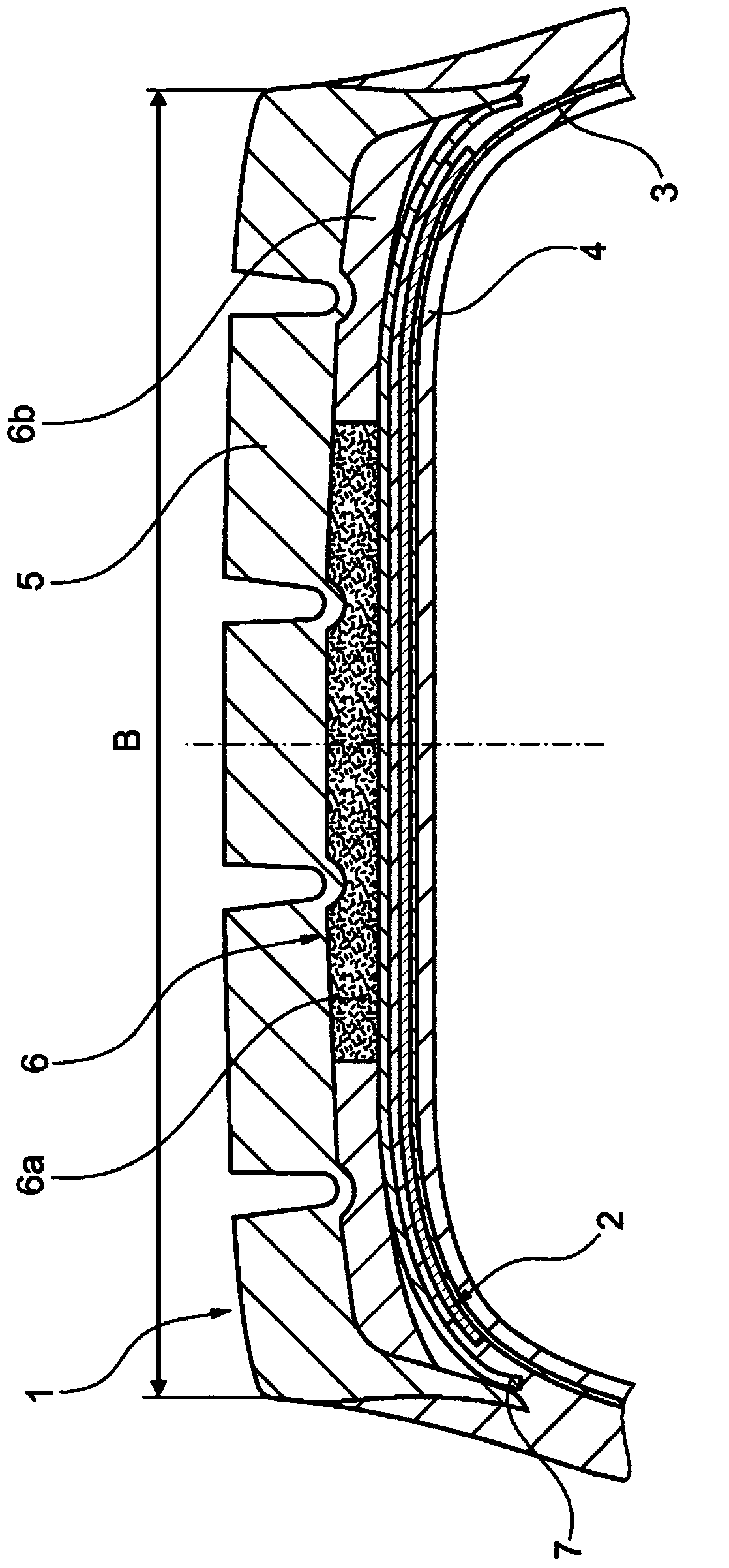
[0031] figure 1 Shows, among the usual elements of a pneumatic tire for automobiles, a tread 1, a belt 2 preferably with two tensioned plies made of reinforcing elements embedded in rubber, preferably of steel cords, a also Radial ply carcass 3 reinforced with reinforcing elements and an airtight inner layer 4 . This belt 2 is covered with belt strips 7 of so-called tape reinforcement elements. The figure shows only the axially outer end section of the sidewall of the tyre. The area of ​​the chafer with the bead wire and bead wire outline is not shown.

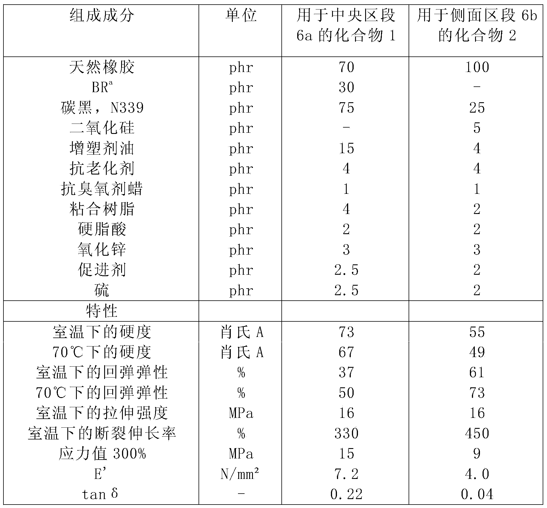
[0032] The tread 1 is composed of a radially outer rubber layer (tread cap 5 ) and a radially inner rubber layer (tread base 6 ). An underlayment (not shown) may also be provided under the tread base 6 . The tread base 6 has a substantially constant thickness of about 2 mm and is divided into three parts in the axial direction so that it consists of a central section 6a and two side sections 6b. The central section 6 a ex...


PUM


Abstract

The invention relates to a pneumatic vehicle tire comprising a radial carcass (3), an at least single-layer belt (2), and a tread (1) that is composed of two layers, a tread cap (5) and a tread base (6), which consist of different rubber mixtures, in a radial direction, said tread base (6) having a central portion (6a) and two lateral portions (6b) that extend at least in a radially outward direction from an axial perspective. The two lateral portions (6b) consist of a rubber mixture that has a lower dynamic modulus of elasticity E' at 55 °C in accordance with DIN 53513 (measured at an extension of 8%) and a lower hysteresis than the central portion (6a) of the tread base (6) for a lower rolling resistance without worsening the handling behavior.

Description

technical field [0001] The present invention relates to a pneumatic vehicle tire, especially for commercial vehicles, having a radial ply carcass, a multilayer belt and a tread comprising in radial direction two Layers of different rubber compounds, a tread cap and a tread base, wherein the tread base, viewed in the axial direction, has at least a central section and two side sections directed radially outwards. Background technique [0002] Pneumatic vehicle tires, both for passenger cars and for commercial vehicles, are generally provided with a two-part tread consisting of a tread cap and a tread base that come into contact with the road surface during tire rolling. The tread cap is made of a wear-optimized rubber compound and the tread base is made of a hysteresis-optimized rubber compound. In addition to the tire's rolling resistance, the tread base also affects its handling (road handling), optimizing one property at the expense of the other. [0003] Pneumatic vehic...

Claims


Application Information

Patent Timeline
Patent Type & Authority Applications(China)
IPC IPC(8): B60C11/00
CPCB60C11/0075B60C11/00B60C2011/0025B60C1/0016Y02T10/86
Inventor 克里斯蒂安·韦伯赖因哈德·路德维希海纳·沃尔克
Owner CONTINENTAL REIFEN DEUTSCHLAND GMBH
Learn More