Molding system for sponge pipe

A sponge and control system technology, applied in metal processing and other directions, can solve the problems of inconsistent inner hole diameter, poor tensile performance, inability to punch long sponges, etc., and achieve the effect of fast punching speed and low sponge loss.

Inactive Publication Date: 2013-12-04
东莞市樟木头雅丰海绵制品加工厂
View PDF5 Cites 9 Cited by
  • Summary
  • Abstract
  • Description
  • Claims
  • Application Information

AI Technical Summary

Problems solved by technology

[0002] Sponge has the characteristics of heat preservation, heat insulation, sound absorption, shock absorption, flame retardant, anti-static, and good air permeability, so it involves various industries. The foamed sponge hose is placed on the element. Because the foamed sponge is soft, inconvenient to shape, and has poor tensile performance, the industry can only cut long strips of sponge into small sections and then punch holes. Multi-segment sponges are spliced ​​and put on the product, but the long sponge cannot be drilled. Due to the constraints of the overall equipment and manufacturing process, it is currently impossible to use a hollow drilling tool with an inner hole diameter of less than 8mm and a length of more than 40cm in the industry. Drilling; now some drilling equipment increases the length of the perforated sponge by extruding the sponge to drill holes, but due to the characteristics of the sponge itself, excessive compression of the sponge will cause the inner hole to be bent and the diameter of the inner hole to be inconsistent, resulting in defective products

Method used


Image

  • Molding system for sponge pipe
  • Molding system for sponge pipe

Examples


Embodiment Construction

[0019] The specific implementation manners of the present invention will be described in detail below in conjunction with the accompanying drawings. Apparently, the described embodiments are only part of the embodiments of the present invention, and other embodiments obtained by those skilled in the art without creative efforts all belong to the protection scope of the present invention.

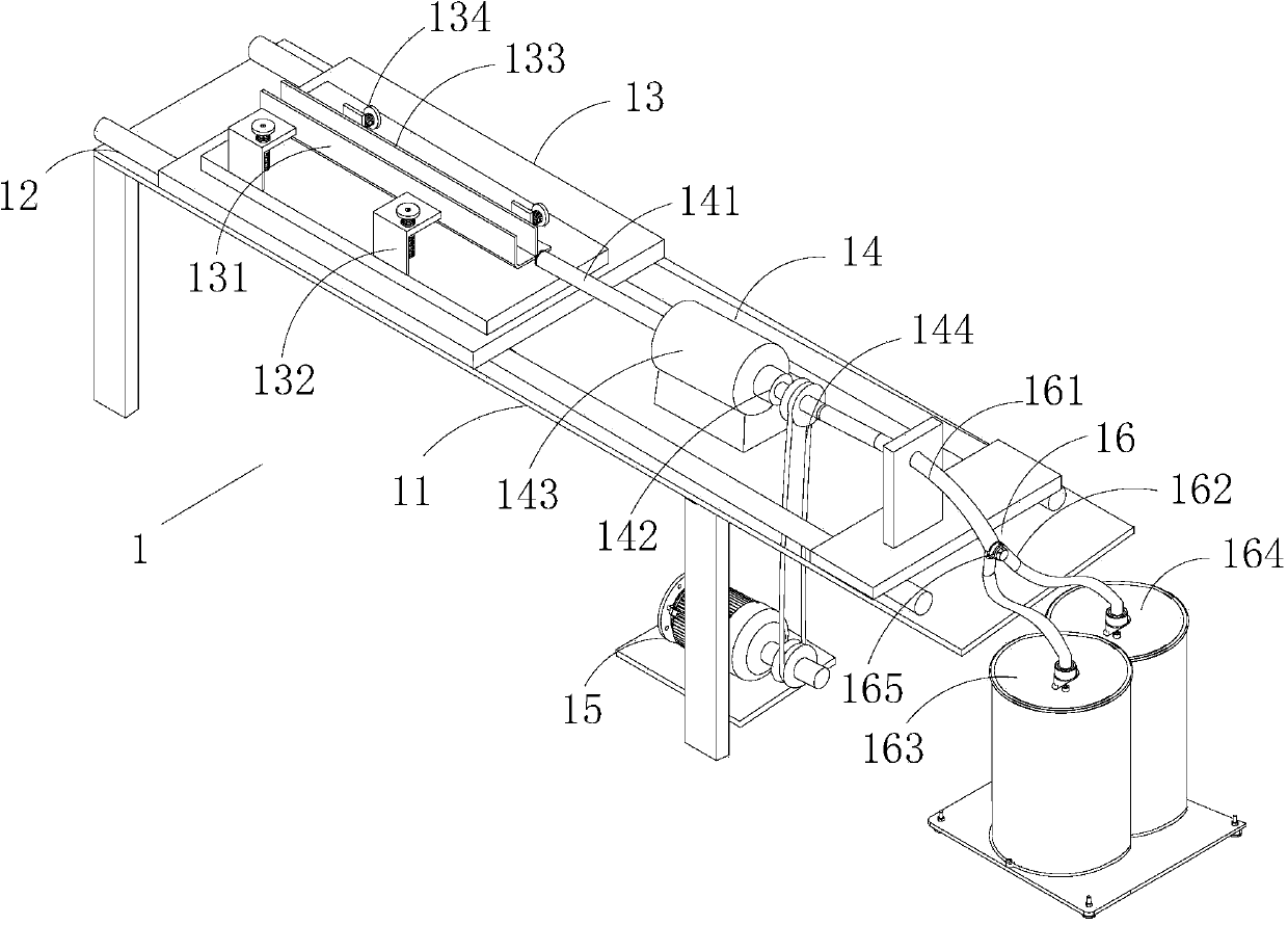
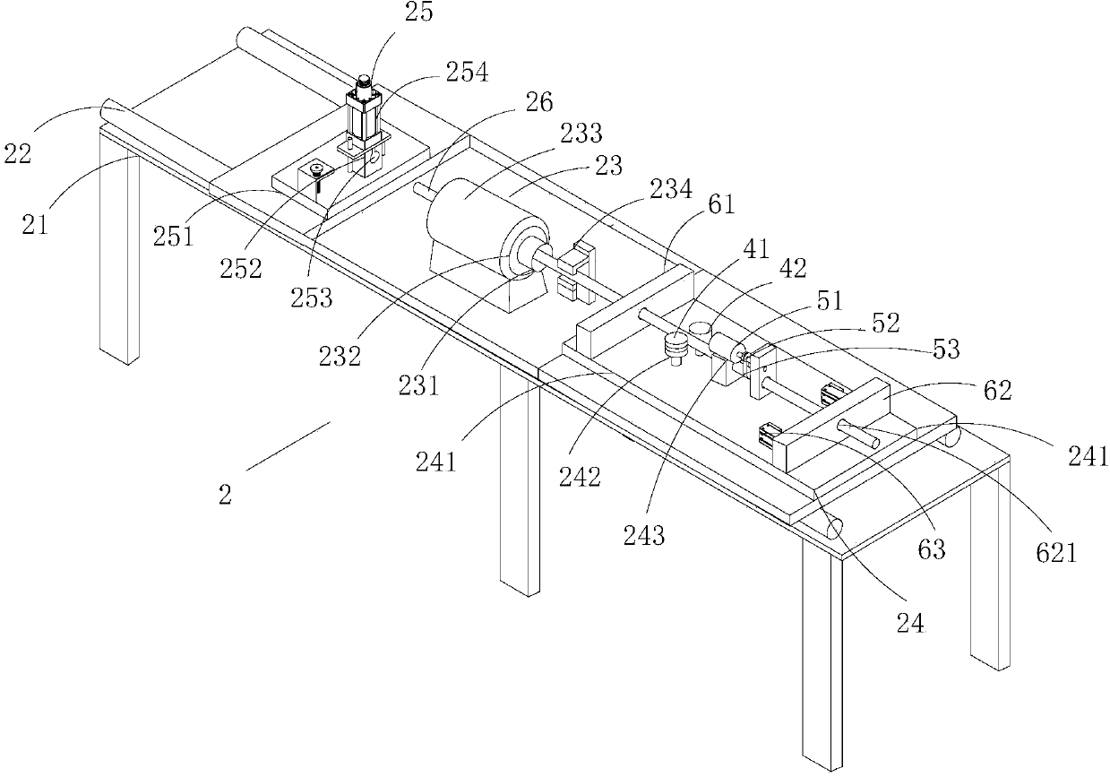
[0020] A forming system for a sponge tube, comprising a punching system 1, a peeling system 2 and a control system, wherein,

[0021] The punching system 1 comprises a punching system bracket 11, a guide rail 12 installed on the punching system bracket, a fixed seat assembly 13 movable along the guide rail 12, a hollow perforating drill assembly 14 arranged opposite to the fixed seat assembly 13, driving The motor 15 of the hollow perforating drill assembly 14, the sponge wool is placed on the fixed seat assembly 13, and the hollow perforated drill assembly 14 drills the sponge wool; its fix...


PUM


Abstract

The invention discloses a molding system for a sponge pipe. The molding system comprises a punching system, a peeling system and a control system, wherein the punching system comprises a punching system bracket, a guide rail, a fixed seat assembly, a hollow punching drilling tool assembly and a power assembly; the guide rail is arranged on the punching system bracket; the fixed seat assembly can move along the guide rail; the hollow punching drilling tool assembly is opposite to the fixed seat assembly; the power assembly drives the hollow punching drilling tool assembly; the peeling system comprises a peeling bracket, a peeling guide rail, a peeling tool assembly, a shaft rod transmission supporting seat, a shaft rod locking supporting seat and a positioning shaft rod; the peeling guide rail is arranged on the peeling bracket; the peeling tool assembly is arranged in the middle of the peeling guide rail; the shaft rod transmission supporting seat is arranged at the front end of the peeling tool assembly and can move along the peeling guide rail; the shaft rod locking supporting seat is arranged at the rear end of the peeling tool assembly and can move along the peeling guide rail; the positioning shaft rod is arranged on the shaft rod transmission supporting seat, can penetrate through the peeling tool assembly by mechanical transmission and is positioned on the shaft rod locking supporting seat. By the adoption of the molding system for the sponge pipe, a longer sponge through hole can be punched without compression of sponge, bad situations such as deformation and distortion of an inner hole of the sponge can be avoided, and the molding system is high in punching speed and low in sponge loss.

Description

technical field [0001] The invention relates to a foaming material punching system, in particular to a foam tube forming system. Background technique [0002] Sponge has the characteristics of heat preservation, heat insulation, sound absorption, shock absorption, flame retardant, anti-static, and good air permeability, so it involves various industries. The foamed sponge hose is placed on the element. Because the foamed sponge is soft, inconvenient to shape, and has poor tensile performance, the industry can only cut long strips of sponge into small sections and then punch holes. Multi-segment sponges are spliced ​​and put on the product, but the long sponge cannot be drilled. Due to the constraints of the overall equipment and manufacturing process, it is currently impossible to use a hollow drilling tool with an inner hole diameter of less than 8mm and a length of more than 40cm in the industry. Drilling; now some drilling equipment increases the length of the perforated...

Claims


Application Information

Patent Timeline
IPC IPC(8): B26F1/16B26D7/01B26D7/27
Inventor 孙丽燕
Owner 东莞市樟木头雅丰海绵制品加工厂
Why Eureka
Try Eureka