

Fitting
A technology for pipe joints and root canals, which is applied in the field of pipe joints, can solve the problems of difficult fastening operations, increased construction costs, and high flange prices, and achieves the effects of easy construction, improved constructability, and low production costs
- Summary
- Abstract
- Description
- Claims
- Application Information
AI Technical Summary
Problems solved by technology
Method used
Image

Examples
Embodiment Construction
[0042] Hereinafter, preferred embodiments of the present invention will be described with reference to the drawings.
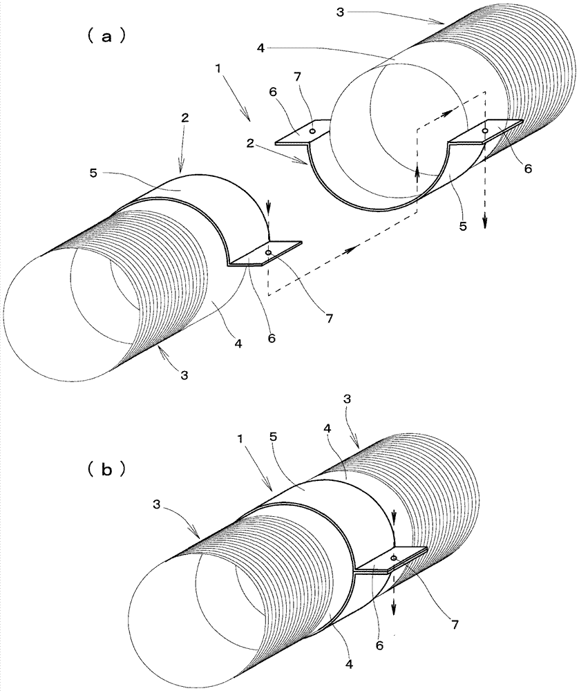
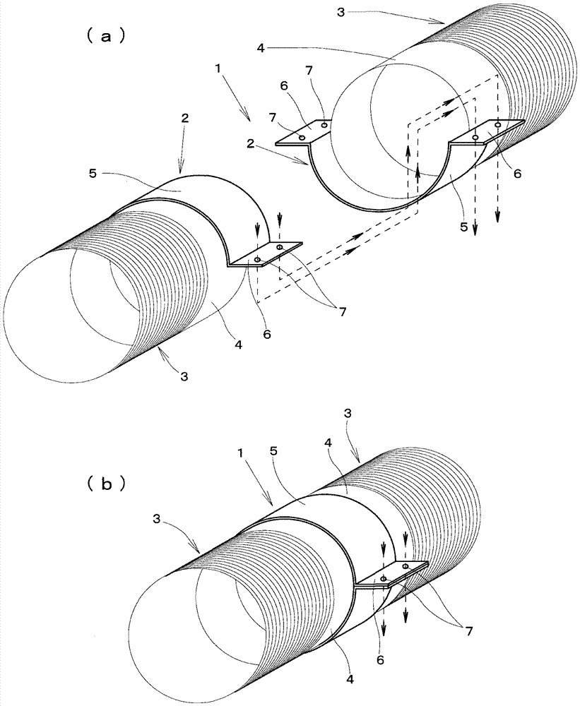
[0043] figure 1 Is a perspective view showing a basic embodiment of the pipe joint of the present invention, figure 1 (a) is a diagram showing the state before connecting the joint, figure 1 (b) is a diagram showing a state after the joint is connected.
[0044] This embodiment is an embodiment corresponding to the second configuration in the "Summary of the Invention" column above. It is a preferred implementation when used in a construction site such as a catchment ditch to connect multiple pipes in a horizontally placed state. the way.
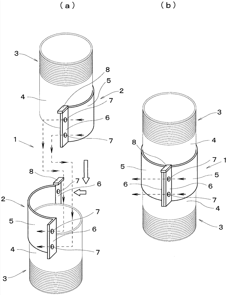
[0045] This embodiment and the embodiments described later have been described as pipe joints for connecting screen tubes, but the pipes to be connected are not limited to screen tubes, and may be ordinary cylindrical steel pipes or resin pipes. . In addition, the pipe joints used in this embodiment and the embodiments described...
PUM
 Abstract
Description
Claims
Application Information