Electric heating device

An electric heating device and electric heating rod technology, applied in electric heating devices, ohmic resistance heating, water heaters, etc., can solve the problems of poor heat conversion efficiency, large energy consumption, waste of energy, etc., to reduce maintenance costs and achieve optimal heat conversion. Efficiency, effect of fast temperature control

Inactive Publication Date: 2013-12-04
ASGARD TECH CO LTD
View PDF8 Cites 3 Cited by
  • Summary
  • Abstract
  • Description
  • Claims
  • Application Information

AI Technical Summary

Problems solved by technology

[0004] Although the above-mentioned previous case M404951 solved the problems of the previous case M371863, such as poor heat conversion efficiency and large energy consumption, there are still problems as follows:
[0005] 1. The alloy electric heating layer is coated on the continuous curved pipe body, so when the alloy electric heating layer fails or is damaged, it is necessary to replace the whole set of continuous curved pipe body, which is quite inconvenient
[0006] 2. The alloy electric heating layer only has the working mode of starting or not starting the whole group, so it is not easy to control the energy output, and there is also the doubt of wasting energy
[0007] 3. Since the alloy electric heating layer is used to heat the liquid, it is not easy for the controller to control the power output, which affects the stability of the output liquid temperature, and the constant temperature effect is not good.
[0008] 4. The heat energy generated by the alloy electric heating layer needs to be transferred to the continuous curved tube first, and then to the liquid inside the tube, so that the heat conversion efficiency is poor and the heat energy is lost quickly
[0009] In view of this, the inventor aimed at the many defects and inconveniences caused by the imperfect design of the above-mentioned electric heating device, and conceived deeply, and actively researched and improved the trial production and developed and designed this case

Method used


Image

  • Electric heating device
  • Electric heating device
  • Electric heating device

Examples


Embodiment Construction

[0040] In order to further explain the technical solution of the present invention, the present invention will be described in detail below through specific examples.

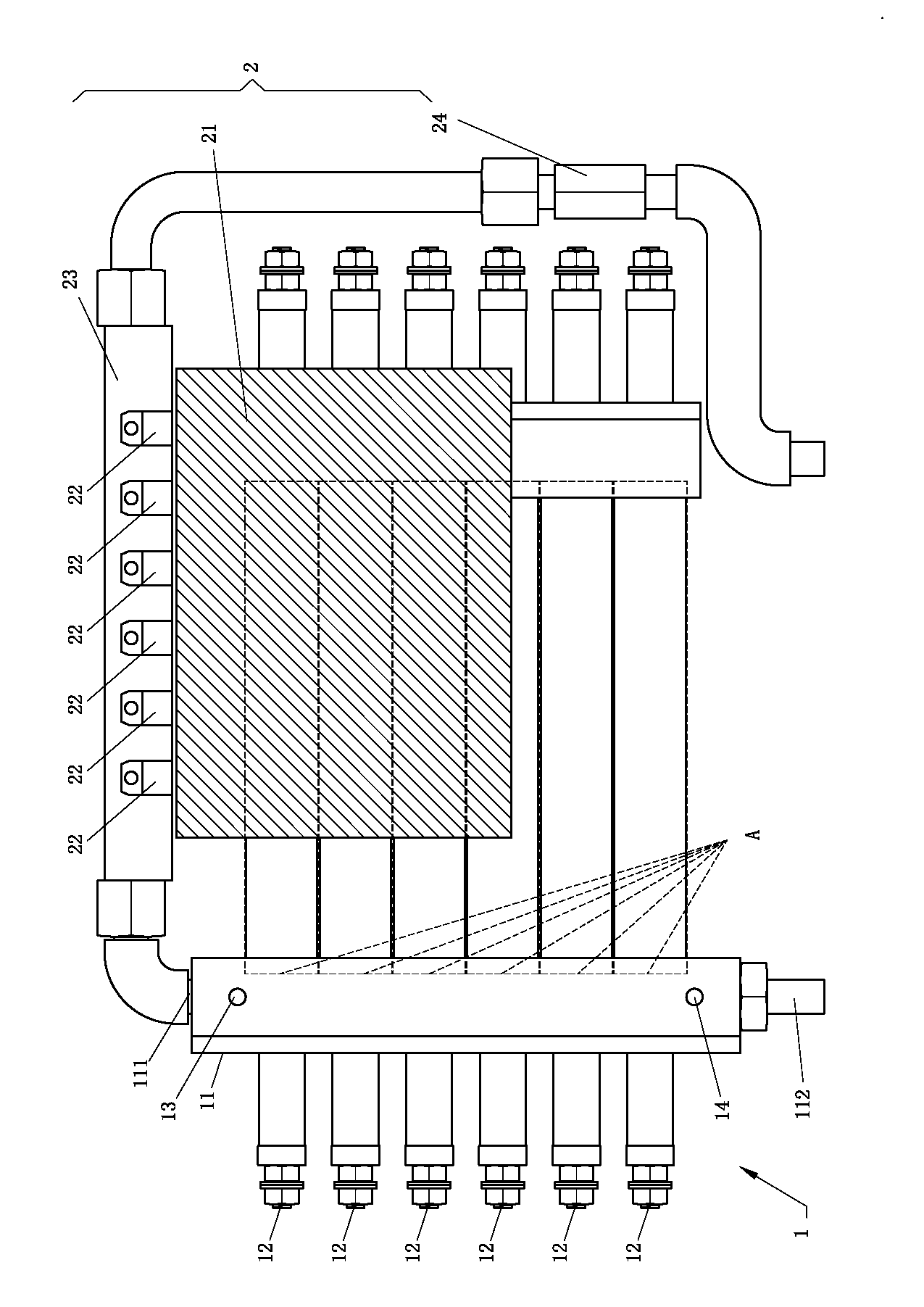
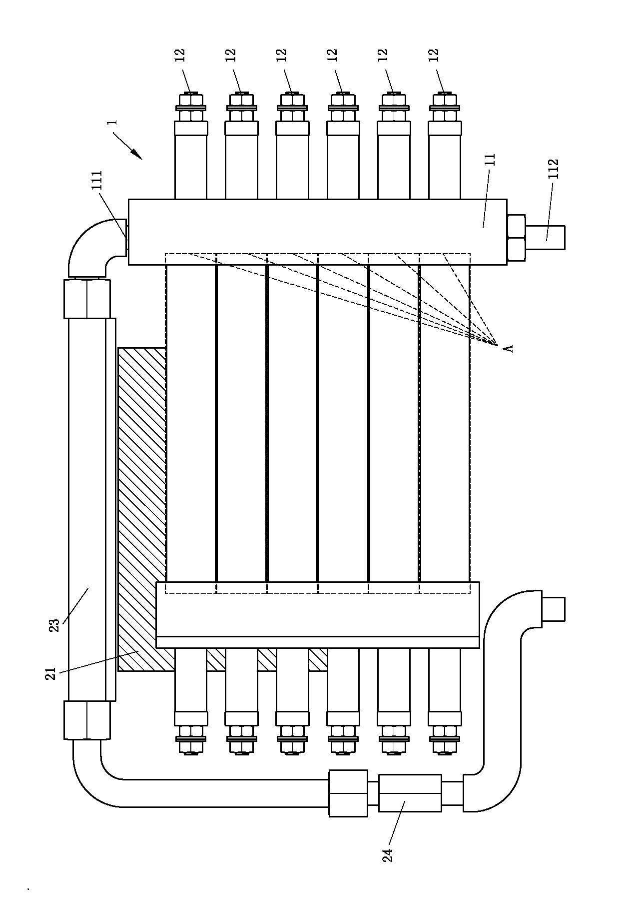
[0041] First, see figure 1 and figure 2 As shown, the preferred embodiment of the present invention is an electric heating device, comprising:

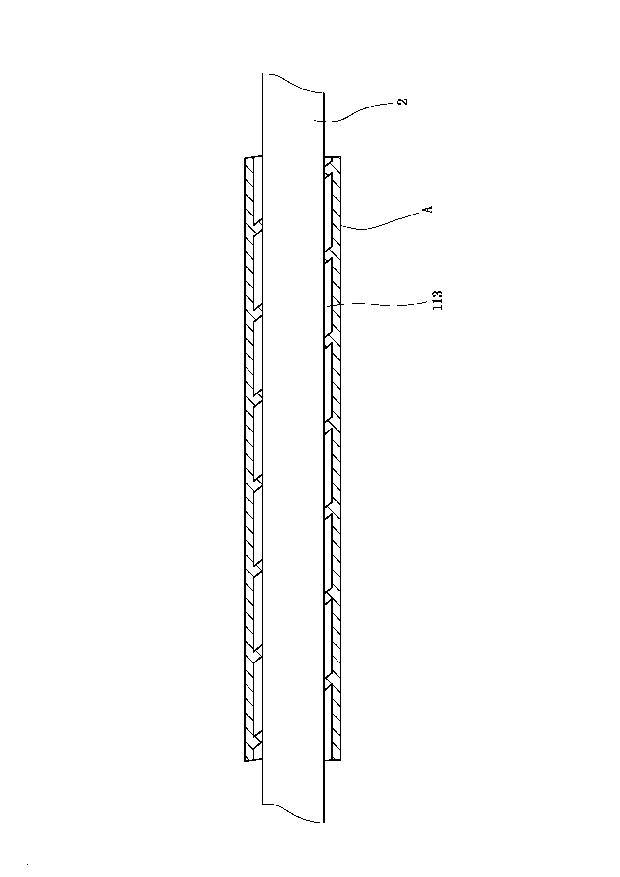
[0042] A heating unit 1 includes a liquid pipeline 11 used as a heating flow channel for the liquid, the aforementioned liquid pipeline 11 is provided with an inlet 111 and an outlet 112, so that the liquid can enter the aforementioned liquid pipeline 11 from the aforementioned inlet 111, and undergo a heating process While flowing out from the outlet 112, the inlet 111 and the outlet 112 of the liquid pipeline 11 are divided into a plurality of heating sections A, and each heating section A houses an electric heating rod 12 respectively, and the aforementioned electric heating rod 12 is used for Supply heat energy to the liquid flowing through the heating section A...


PUM


Abstract

An electric heating device includes a main tube which includes multiple heating areas. Each heating area has a hating bar received therein to provide thermal energy to the liquid passing through the heating areas and to increase the temperature of the liquid. A control unit has multiple control members and each control member is electrically connected to and controls one of the heating bars. Each of the control members has a heat dissipating tube connected thereto. The multiple heating areas are cooperated respective heating bars to increase the contact areas between the liquid and the heating bars to quickly increase the temperature of the liquid.

Description

technical field [0001] The invention relates to an electric heating device, in particular to an electric heating device which utilizes a plurality of heating sections and a plurality of electric heating rods to heat a liquid to improve heat conversion efficiency. Background technique [0002] Existing electric heating devices such as the patent case of Taiwan New Patent Announcement No. M371863 "electric water heater with turbulent flow structure" have heating components, coils and heat pipes inside the main body for heating. The heat pipe heats up the liquid inside the body. However, the body contains a large amount of liquid, so that the heating process takes more time and requires a lot of energy to heat the liquid to the set temperature. In addition to poor heat conversion efficiency In addition, the long heating time and energy consumption are a big problem. [0003] Also, as the patent case of "Liquid Heater" in Taiwan New Patent Announcement No. M404951, it mainly in...

Claims


Application Information

Patent Timeline
Patent Type & Authority Applications(China)
IPC IPC(8): F24H1/10F24H9/18F24H9/20F24H9/00
CPCF24H1/102F24H9/1818H05B3/42H05B2203/021
Inventor 林祐瑱
Owner ASGARD TECH CO LTD
Why Eureka
Try Eureka