Ultrahigh frequency antenna array partial discharge detection system

A technology of partial discharge detection and antenna array, applied in the direction of testing dielectric strength, etc., can solve the problems of different propagation characteristics of electromagnetic waves

Inactive Publication Date: 2013-12-04
STATE GRID CORP OF CHINA +2
View PDF1 Cites 12 Cited by
  • Summary
  • Abstract
  • Description
  • Claims
  • Application Information

AI Technical Summary

Problems solved by technology

However, due to the different characteristics of the internal structure of power equipment and the different propagation characteristics of electromagnetic waves generated by partial discharge in power equipment, the use of ultra-high frequency methods to locate the specific location of partial discharge defects in equipment is still in the exploratory stage

Method used


Image

  • Ultrahigh frequency antenna array partial discharge detection system
  • Ultrahigh frequency antenna array partial discharge detection system
  • Ultrahigh frequency antenna array partial discharge detection system

Examples


Embodiment

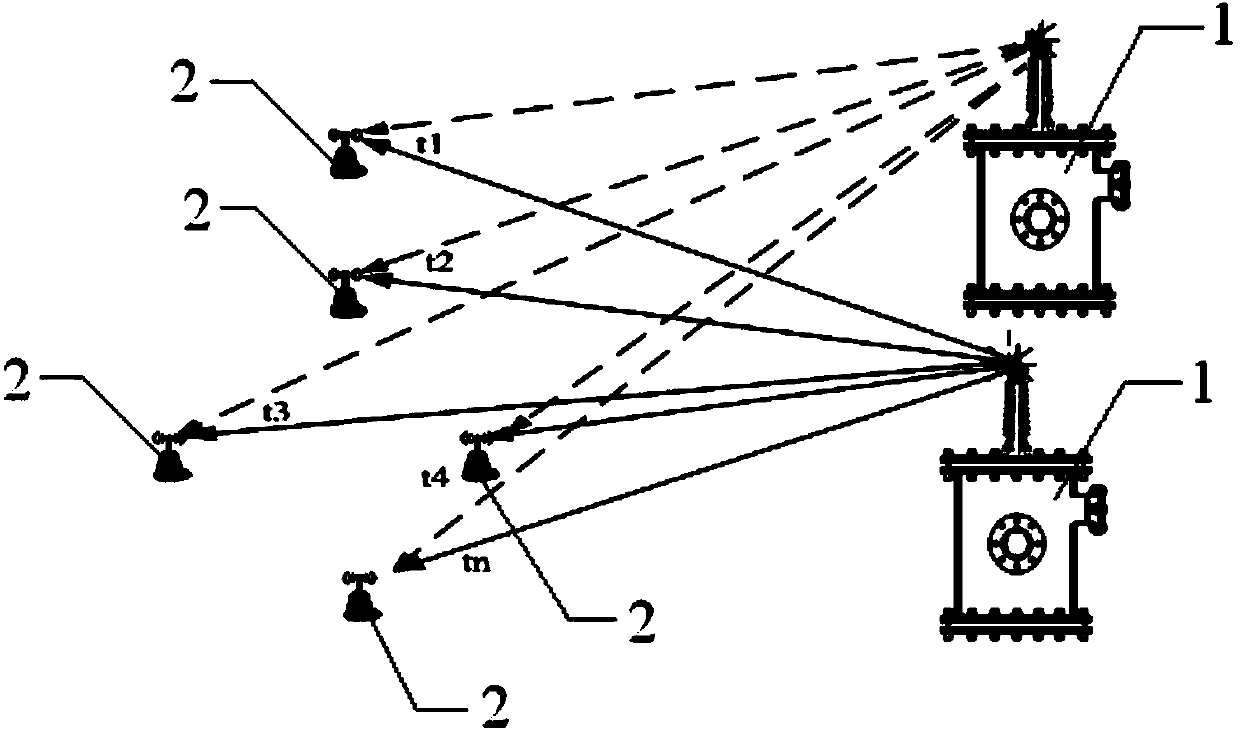
[0022] UHF antenna array partial discharge detection system, its structure is as follows figure 1 As shown, the detection system includes a partial discharge source 1 and a partial discharge sensor 2 . Among them, the partial discharge source 1 is a discharge source that emits UHF signals, and is installed in the substation, and the partial discharge sensors 2 are arranged around the partial discharge source 1, and the distance between each partial discharge sensor 2 and the partial discharge source 1 is equal to Not the same, the partial discharge source 1 and the partial discharge sensor 2 are connected via a high-frequency signal. The partial discharge sensor 2 used is an ultra-wideband antenna sensor, and there are 4 or more, and 5 are used in this embodiment, and the above-mentioned sensors constitute an ultra-wideband antenna array.

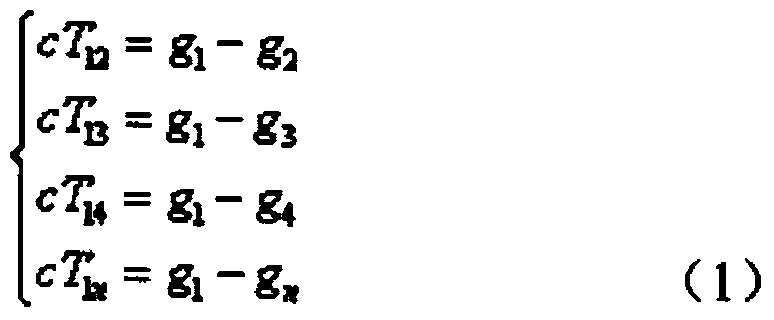
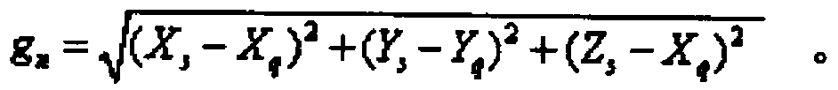
[0023] The moment when the partial discharge signal propagates from a certain point of the power transmission and transformation equipmen...


PUM


Abstract

The invention relates to a ultrahigh frequency antenna array partial discharge detection system comprising a partial discharging source and partial discharging sensors. The partial discharging source sends ultrahigh frequency signals and is arranged in a substation; the partial discharging sensors are arranged at the periphery of the partial discharging source, and the distances between each partial discharging sensor and the partial discharging source are different. Compared with the prior art, a principle of minimum optical path differences is utilized, transmit features of ultrahigh frequency electromagnetic signals produced by partial discharging source in the air are studied, influences on signal transmitting by positions of substation equipment are considered, and partial discharging positioning can be realized according to delay of signals reaching different detecting points; determination of the time of the first wave of the signals, method for acquiring the signal delay and realization of accurate positioning of discharging signals based on discharging signal delay sequence analysis and spatial analysis, by the methods of signal first wave value, power accumulation, time and space calculation and minimum power value, are studied.

Description

technical field [0001] The invention relates to an insulation fault detection system, in particular to an ultra-high frequency antenna array partial discharge detection system. Background technique [0002] Insulation fault is one of the most important possible faults in the operation of power equipment. Before the insulation fault of power equipment occurs, there will generally be a gradual partial discharge process, which will eventually lead to insulation breakdown. If partial discharge monitoring and diagnosis of operating equipment can be carried out during this process, partial discharge signals can be detected in time, and defects can be dealt with in advance, so that the occurrence of insulation breakdown faults can be effectively avoided. The positioning of the partial discharge location is also helpful to formulate a more targeted maintenance treatment plan, reduce power outage time, and improve maintenance efficiency. [0003] At present, the partial discharge de...

Claims


Application Information

Patent Timeline
Patent Type & Authority Applications(China)
IPC IPC(8): G01R31/12
Inventor 沈晓岚李亦农
Owner STATE GRID CORP OF CHINA
Why Eureka
Try Eureka