Air-tightness joint with double female ends

A technology of airtightness and outer conductor, which is applied in the direction of electrical components, two-part connection devices, contact parts, etc., and can solve problems such as poor index stability, poor environmental resistance, and inability to achieve airtightness

Inactive Publication Date: 2013-12-04
安徽蓝麦通信股份有限公司
View PDF6 Cites 2 Cited by
  • Summary
  • Abstract
  • Description
  • Claims
  • Application Information

AI Technical Summary

Problems solved by technology

The structure of this method is too simple, and there are three major disadvantages: one is that the product cannot achieve airtightness, because the insulator 7 is provided with the cutting seam 71 of the card jack 8 in the radial direction, even if it is installed in the casing 9, it cannot The complete sealing of the cutting seam 71 is realized, so that the product cannot achieve airtightness; the second is that the index stability is poor, because the insulator 7 and the shell 9 cannot be effectively fixed, resulting in the insulator 7 being radially and axially in the shell 9. The third is the poor environmental resistance. Since the airtightness cannot be achieved, corrosive gases and pollutants cannot be prevented from entering the interior of the connector, causing corrosion inside the connector and reducing the service life of the product.

Method used


Image

  • Air-tightness joint with double female ends
  • Air-tightness joint with double female ends
  • Air-tightness joint with double female ends

Examples


Embodiment

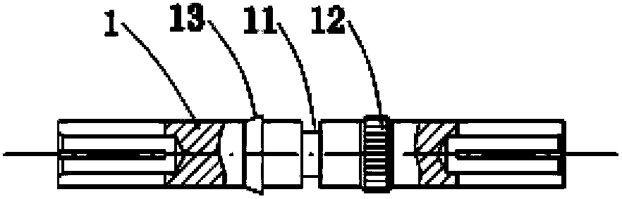
[0019] Example: Combined Figures 1A-1C , the airtight N-type double cathode of the present embodiment, which includes:

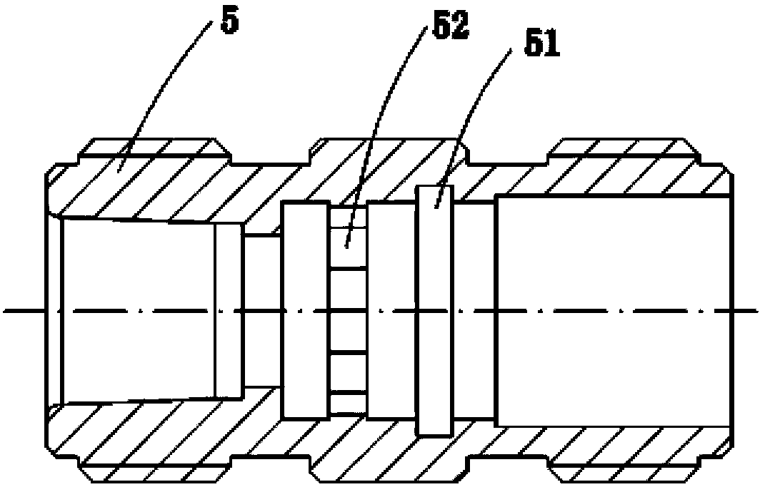
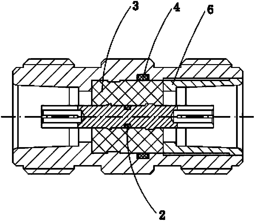
[0020] The inner conductor 1 in the center and the insulating medium 3 coaxially sleeved outside the inner conductor, the outer conductor 5 with a stepped hole cavity, the insulating medium 3 is arranged in the stepped hole of the outer conductor, and the insulating medium 3 and the outer conductor 5 coaxial settings.

[0021] A fixed block 6 is tightly connected to the stepped orifice of the outer conductor, and the fixed block 6 and the stepped surface of the stepped hole form an axial limit at both ends of the insulating medium.

[0022] There is a circumferential limit structure between the outer circumference of the insulating medium 3 and the inner cavity of the outer conductor 5. Specifically, a plurality of bosses 52 are arranged in the axial direction on the inner cavity wall of the outer conductor, and the plurality of bosses are located in the i...


PUM


Abstract

The invention discloses an air-tightness joint with double female ends which comprises an inner conductor at the center, an insulating medium coaxially sleeved outside the inner conductor, and an outer conductor with a stepped hole type inner cavity. The insulating medium is arranged in the stepped hole of the outer conductor and is coaxially arranged together with the outer conductor; a fixing block is connected to an opening part of a stepped hole of the outer conductor in a close fit manner; the fixing block and the step surface of the stepped hole form axial limitation at two ends of the insulating medium. The air-tightness joint with double female ends has a simple structure, good air tightness, strong environment tolerance, reliable mechanical performances, excellent electric performances and high assembling efficiency, and is suitable for production on a large scale.

Description

Technical field: [0001] The invention relates to an airtight double cathode, in particular to an airtight N-type double cathode. Background technique: [0002] At present, a simple wrap-around structure is commonly used for N-type double cathodes. Such as Figures 2A-2C It is a snap-in structure, and the specific operation is to first use special tooling to spread the insulator 7 along the cutting seam 71, then snap the jack 8 into the inner hole of the insulator 7, and then use special tooling to crimp the insulator 7 to the shell 9 , thus producing a traditional N-type double negative. The structure of this method is too simple, and there are three major disadvantages: one is that the product cannot achieve airtightness, because the insulator 7 is provided with the cutting seam 71 of the card jack 8 in the radial direction, even if it is installed in the casing 9, it cannot The complete sealing of the cutting seam 71 is realized, so that the product cannot achieve airtig...

Claims


Application Information

Patent Timeline
Patent Type & Authority Applications(China)
IPC IPC(8): H01R13/52H01R13/20H01R13/213H01R13/40H01R24/38
Inventor 邓腾飞
Owner 安徽蓝麦通信股份有限公司
Why Eureka
Try Eureka