
Shielded integrated connector modules and assemblies and methods of making the same

A technology of connector modules and shielding parts, which is applied in the field of integrated connector modules, can solve the problems of overall performance degradation of connector assemblies, unshielded electrical short-circuit reliability, and interference signals, etc.

Active Publication Date: 2016-12-28
PULSE ELECTRONICS
View PDF11 Cites 0 Cited by
  • Summary
  • Abstract
  • Description
  • Claims
  • Application Information

AI Technical Summary

Problems solved by technology

However, this method of using only the outer "wrap" of the noise shield has several disadvantages
In particular, this arrangement does not provide complete or even near-complete shielding of the individual connectors in the assembly because the bottom surface of the connector housing typically remains largely unshielded (due to the Consideration of reduced reliability of electrical short circuit between)
Additionally, the ports in which the modular plugs are received are unshielded, whereby the front of the module remains largely open
These "gaps" in the shield degrade the overall performance of the connector assembly by reducing the signal-to-noise ratio (SNR) from the increased noise
[0006] Additionally, such wrap-around outer shields do not address the problem of noise leakage across connectors, where noise radiated by components of one connector in an assembly interferes with the signal of the other connector, and vice versa
Noise leakage across connectors is especially problematic as data rates through integrated connector modules increase and the density of electronic / electrical components within the assembly increases
[0007] Since manufacturers and consumers in general are very sensitive to the cost and pricing of integrated connector modules, there is a constant anxiety about producing an integrated connector module with the best possible (noise) performance for a given data rate and at the lowest possible cost

Method used


Image

  • Shielded integrated connector modules and assemblies and methods of making the same
  • Shielded integrated connector modules and assemblies and methods of making the same
  • Shielded integrated connector modules and assemblies and methods of making the same

Examples


Embodiment Construction

[0032] Referring now to the drawings, like numerals represent like parts throughout.

[0033] As used herein, the terms "electrical component" and "electronic component" are used interchangeably and mean a component adapted to provide some electrical and / or signal conditioning function, including, but not limited to, current limiting reactors ("choke coils") ”), transformers, filters, transistors, toroidal tubes, inductors (coupled or otherwise), capacitors, resistors, operational amplifiers, processors, controllers, and diodes, whether discrete or integrated, regardless of Whether it is alone or in combination.

[0034] As used herein, the term "integrated circuit" shall include any type of integrated device having any function, whether single or multiple die, or small or large scale, including but not limited to application specific integrated circuits (ASICs) ), Field Programmable Gate Arrays (FPGAs), digital processors (eg DSPs, CISC microprocessors or RISC processors) an...


PUM


Abstract

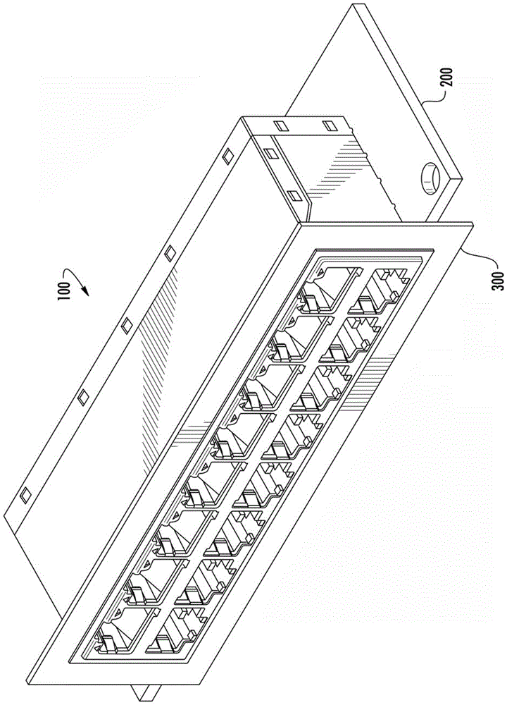
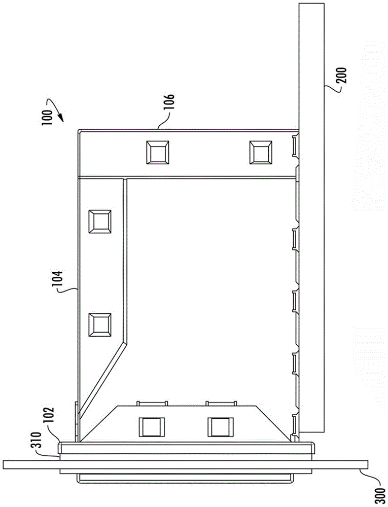
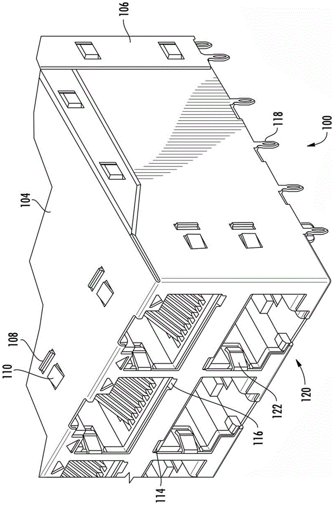
The present invention discloses high electrical isolation connector apparatus and methods. In one embodiment, an integrated connector module ICM is disclosed. The ICM includes several adjacent electronic subassemblies shielded through the use of intervening body shields. The insert body shield beneficially increases electrical isolation between adjacent subassemblies, thereby further mitigating possible electrical noise. The insert body shield is configured to be received within a slot formed in the connector housing. Also included is an internal shield received in the slot of the insertion body of the electronic subassembly, thereby effectively shielding adjacent component receiving pockets from each other. Methods and apparatus for utilizing these shielded ICMs are also disclosed. For example, telecom / networking devices incorporating these ICMs are also disclosed.

Description

[0001] priority [0002] This application claims the benefit of priority to commonly-owned U.S. Patent Application Serial No. 13 / 797,527, filed March 12, 2013, of the same title, which claims the same title, filed April 27, 2012 Priority benefit of commonly owned US Provisional Patent Application No. 61 / 639,739, each of which is incorporated herein by reference in its entirety. technical field [0003] The present invention relates generally to integrated connector modules, and in particular to an improved design and method of manufacturing integrated connector modules with noise shielding and internal electronic components. Background technique [0004] Integrated connector modules are well known in the field of electronic connectors. There are several major considerations in the design and manufacture of this integrated connector module, including (not limited to): (i) shielding the individual connectors from externally generated electromagnetic interference (EMI) or "no...

Claims


Application Information

Patent Timeline
IPC IPC(8): H01R13/6587H01R43/00
CPCH01R13/514H01R13/6586H01R13/6658H01R13/6581
Inventor 托马斯·拉斯孔穆罕默德·萨布里
Owner PULSE ELECTRONICS
Learn More