Tension-resistance wire clamp

A tension clamp, one-line technology, applied in the direction of adjusting/maintaining mechanical tension, etc., can solve the problem of high strength, achieve the effect of good contact area, ensure stability, and high current carrying capacity

Inactive Publication Date: 2013-12-04
HENAN KOSEN CABLE
View PDF3 Cites 2 Cited by
  • Summary
  • Abstract
  • Description
  • Claims
  • Application Information

AI Technical Summary

Problems solved by technology

higher strength

Method used


Image

  • Tension-resistance wire clamp
  • Tension-resistance wire clamp

Examples


Embodiment Construction

[0011] The present invention will be further described below in conjunction with the accompanying drawings and specific embodiments.

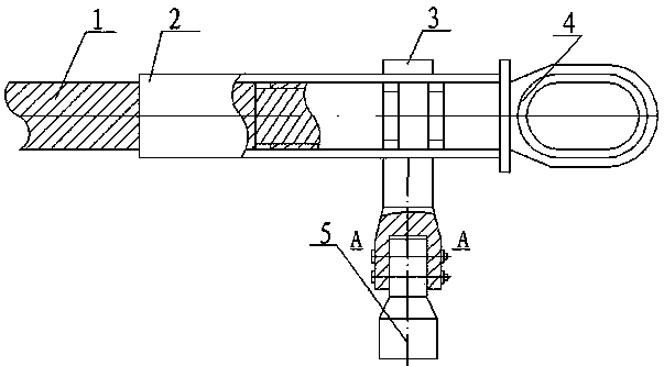
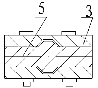
[0012] Such as figure 1 and figure 2 As shown, the tension clamp of the present invention includes a clamp body 2, a steel anchor 4 and a drainage tube 5, and is characterized in that the clamp body 2 is provided with a U-shaped drainage plate with a built-in groove at a selected position 3. The drainage plate 3 has a split jaw; one end of the drainage tube 5 is a flat plate, and there is a protrusion corresponding to the groove of the drainage plate 3 in the flat plate, and one end is a hollow dead tube, and the hollow dead tube A jumper can be set in the

[0013] The U-shaped diversion plate 3 is welded or directly cast on the tension clamp body 2 . The U-shaped drainage plate 3 is provided with keyholes, and the matching section of the drainage tube 5 and the drainage plate 3 is provided with corresponding locking holes. When the drainag...


PUM


Abstract

The invention discloses a tension-resistance wire clamp which comprises a wire clamp body, a steel anchor and a drainage tube. A U-shaped drainage plate with an internally-formed groove is arranged at the designated position of the wire clamp body, the drainage plate is provided with a forked clamping opening, a panel is arranged at one end of the drainage tube, a protrusion corresponding to the groove of the drainage plate is arranged in the panel, a hollow blind tube is arranged at one end of the panel, and a wire jumper can be arranged in the hollow blind tube. A lock hole is formed in the U-shaped drainage plate, a corresponding lock hole is formed in the segment where the drainage tube is matched with the drainage plate, when the drainage tube is inserted into the drainage plate, the drainage tube is locked by a bolt, and good locking is obtained. According to the tension-resistance wire clamp, the drainage tube for containing the wire jumper and the drainage plate have the excellent contact area, the stability of current transmission is ensured, the tension-resistance wire clamp is particularly suitable for being used for mutual connection between a wire on an iron tower and the wire jumper, the higher current-carrying capacity is met, the protrusion and the groove which are mutually matched are arranged at the position where the drainage plate is locked with the drainage tube, the matching strength of the drainage plate and the drainage tube is increased, and the tension-resistance wire clamp can bear stronger wind.

Description

technical field [0001] The invention relates to a strain-resistant clamp, which belongs to matching fittings for power lines. Background technique [0002] When the overhead transmission line passes through the tension tower, it needs to be fixed on the tension insulator of the tension tower, and the jumper is used to drain the overhead transmission line to complete the spanning connection of the overhead transmission line. At this time, the tension line is required The clamp completes the fixing between the overhead transmission line and the tension insulator, as well as the drainage of the overhead transmission line. The strain clamp includes a strain clamp body, a steel anchor, a drainage plate and a drainage tube. The drainage of the overhead transmission line by the tension clamp is mainly by inserting the steel core in the overhead transmission line into the tension clamp body, and connecting the other end of the drainage plate combined with the tension clamp body...

Claims


Application Information

Patent Timeline
Patent Type & Authority Applications(China)
IPC IPC(8): H02G7/02
Inventor 不公告发明人
Owner HENAN KOSEN CABLE
Why Eureka
Try Eureka