Oil cooling electric driving force rotor structure

A technology of rotor structure and driving force, applied in the field of electric motors, can solve the problems of high temperature demagnetization, high fuel consumption, limited power density, etc., and achieve the effect of high oil usage rate, low consumption and weight reduction

Inactive Publication Date: 2021-08-03
ZHEJIANG LEAPMOTOR TECH CO LTD
View PDF8 Cites 7 Cited by
  • Summary
  • Abstract
  • Description
  • Claims
  • Application Information

AI Technical Summary

Problems solved by technology

In this solution, the fuel consumption is high, there is a risk of high temperature demagnetization, and the power density is limited

Method used


Image

  • Oil cooling electric driving force rotor structure
  • Oil cooling electric driving force rotor structure
  • Oil cooling electric driving force rotor structure

Examples


Embodiment

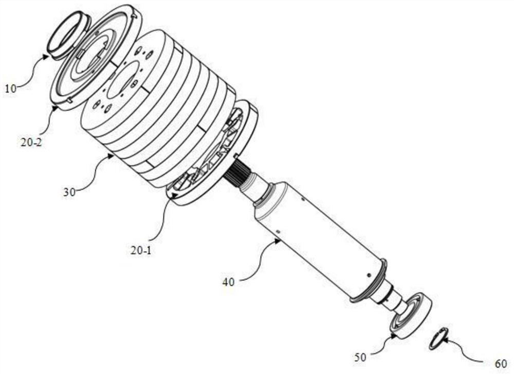
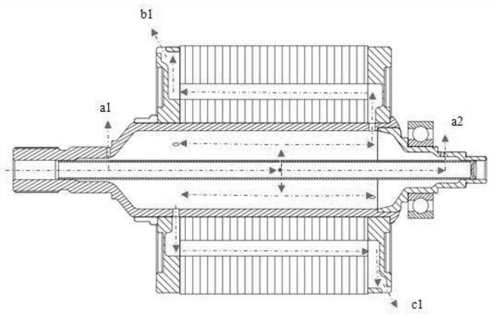
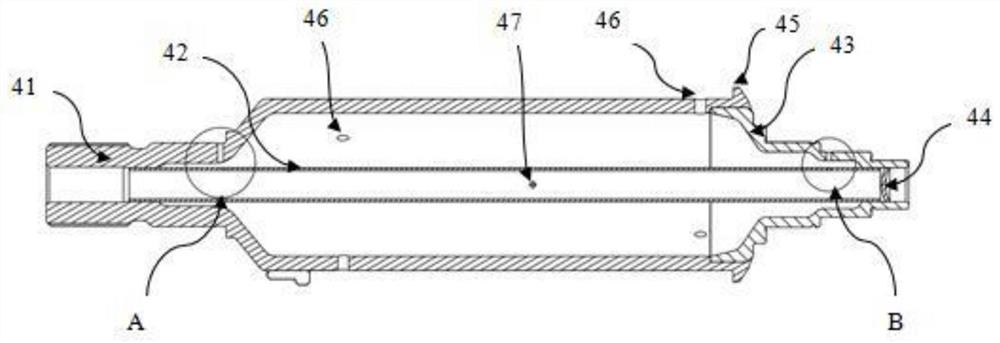
[0025] Such as figure 1 In the illustrated embodiment, an oil-cooled electric drive rotor structure includes a motor shaft 40 and a rotor core assembly mounted on the motor shaft. The motor shaft includes a main shaft body 41, an inner insertion tube 42, a shaft head 43 and stuffy 44, such as Figure 3 to Figure 5 As shown, the main shaft body is made of formed steel pipe raw material, which is processed by rotary forging, and the shaft head is forged into a blank for forming. Two oil holes 49, the main shaft body and the shaft head are press-fitted with a circular seam interference fit, and then the end is riveted by a pressure riveting process to prevent the shaft head from coming out; the inner tube is made of aluminum pipe, and the inner tube Press-fitted in the cavity, the side of the inner insertion tube is provided with a main oil outlet 47, a first oil outlet and a second oil outlet, and the first oil outlet and the second oil outlet are connected with the first oil h...


PUM


Abstract

The invention discloses an oil cooling electric driving force rotor structure, and the structure comprises a motor shaft and a rotor iron core assembly installed on the motor shaft; the motor shaft comprises a main shaft body and an inner insertion pipe, the main shaft body is provided with a cavity and a main oil hole communicated with the cavity, the inner insertion pipe is inserted in the cavity, the side surface of the inner insertion pipe is provided with a main oil outlet, and the main oil outlet is communicated with the main oil hole; an inner cavity of the inner penetrating pipe is communicated with a cavity of the main shaft body through the main oil outlet, one end of the inner inserting pipe is sealed, the other end of the inner inserting pipe is open, the rotor iron core assembly is provided with an oil channel, one end of the oil channel is communicated with the main oil hole of the main shaft body, the other end of the oil channel is communicated to an air gap in the periphery of the rotor iron core assembly, and the hole diameter of the main oil hole is larger than that of the main oil outlet. According to the scheme, the cooling and heat dissipation effects of the motor are greatly improved, and the power density is instantly improved; meanwhile, the oil liquid passes through the structure of the inner insertion pipe to avoid volume oil of the main shaft, the stator is further cooled after the rotor is cooled by the oil liquid, the oil consumption of the electric drive assembly is reduced, and the high-temperature demagnetization risk is avoided.

Description

technical field [0001] The invention relates to the field of electric motors, in particular to an oil-cooled electric drive rotor structure. Background technique [0002] As the core technology of new energy vehicles, the electric powertrain is becoming increasingly integrated and developing in the direction of high power density. (1) Due to the limitation of mechanical strength and loss, it is difficult to increase the power limit in the prior art; (2) Because the stator and rotor are immersed in the oil, the oil consumption of the prior art is large; (3) There is a high temperature of the rotor Risk of demagnetization, for example, an "oil-cooled motor that can isolate the space where the motor stator and rotor are located" disclosed in the Chinese patent literature, its announcement number CN109194037A, is set in the air gap 6 between the motor stator 1 and the rotor 3 The isolation sleeve assembly 5, the isolation sleeve 501 is a cylindrical structure with a rib 504 on ...

Claims


Application Information

Patent Timeline
Patent Type & Authority Applications(China)
IPC IPC(8): H02K1/20H02K7/00H02K9/19H02K5/16
CPCH02K1/20H02K7/003H02K9/19H02K5/161
Inventor 骆忠贤陈晓宇姚伟科汤卫平吴元强
Owner ZHEJIANG LEAPMOTOR TECH CO LTD
Why Eureka
Try Eureka