
Yarn winding device

A winding device and yarn technology, which are applied in the directions of transportation and packaging, transportation of filamentous materials, and thin material processing, etc., can solve the problems of yarn unwinding and looping, yarn breakage, and package winding stop. , to achieve the effect of preventing looping, preventing yarn breakage, and preventing poor lead-out

Inactive Publication Date: 2016-04-13
MURATA MASCH LTD
View PDF6 Cites 0 Cited by
  • Summary
  • Abstract
  • Description
  • Claims
  • Application Information

AI Technical Summary

Problems solved by technology

[0004] In the yarn accumulating device, if the yarn is unwound from the yarn accumulating device to the package, the yarn breakage occurs, and the winding of the package stops.
The conventional yarn accumulating device represented by Patent Document 1 has a structure in which the yarn wound last pushes up the yarn wound earlier, so hairiness and hairiness may be entangled, resulting in a loss of Occurrence of decoupling during winding
In addition, due to the structure in which the yarn wound first pushes up the yarn wound earlier, hairiness and hairiness may become entangled when drawing out the yarn end accumulated on the yarn accumulating device. lead to bad situations

Method used


Image

  • Yarn winding device
  • Yarn winding device
  • Yarn winding device

Examples


Embodiment Construction

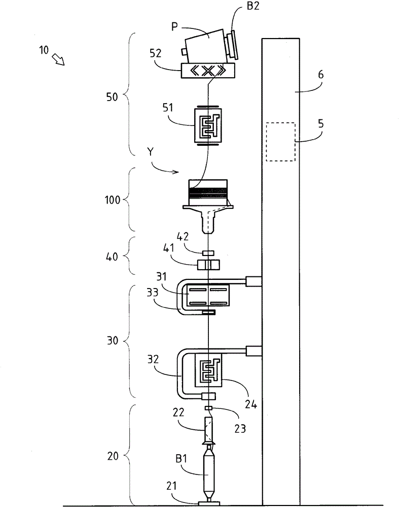
[0034] use figure 1 , the winding unit 10 of the first embodiment of the automatic winding device of the present invention will be described.

[0035] The winding unit 10 is a device that removes yarn defects on the yarn supplying bobbin B1 around which the yarn Y spun by the spinning machine is wound, and forms a package P for winding. The winding units 10 are arranged side by side along the longitudinal direction of the machine bed of the automatic winder.

[0036] The structure of the winding unit 10 will be described.

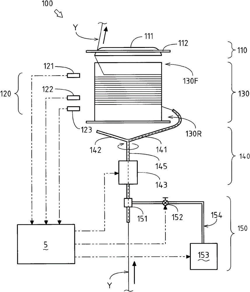
[0037] The winding unit 10 includes a controller 5 , a frame 6 , a yarn supplying unit 20 , a yarn joining unit 30 , a yarn defect detecting unit 40 , a yarn accumulating device (accumulator) 100 , and a winding unit 50 .

[0038] The frame 6 is a device that supports each device constituting the winding unit 10 . The frame 6 supports the yarn supplying unit 20, the yarn joining unit 30, the yarn defect detecting unit 40, the yarn accumulating device 100...


PUM


Abstract

Provided is a yarn winding device that can prevent the occurrence of sluffing. A winding unit (10), while eliminating the threading defects of a yarn feeding bobbin (B1) around which is wound a yarn (Y) that is spun by a fine spinning machine, winds a package (P). The winding unit (10) comprises a yarn accumulating device (100) which winds the yarn (Y) from the yarn feeding bobbin (B1) and accumulates the wound yarn. The yarn accumulating device (100) comprises the following: a yarn accumulating part (130) which accumulates the yarn (Y); and a winding part (140) which, while rotating, winds the yarn (Y) around the yarn accumulating part (130). The yarn accumulating part (130) comprises the following: a yarn accumulating body (belt outer side) (132F) around which the yarn (Y) is wound; and a drive pulley (134) which maintains an equidistant space between yarns (Y) to be wound and supplies the yarn (Y) that is wound around the belt outer side (132F) from a winding side (130R) to a unwinding side (130F).

Description

technical field [0001] The present invention relates to the technology of yarn winding devices. Background technique [0002] The yarn winding device is known as a device for rewinding a yarn supplying bobbin on which yarn spun by a spinning machine is wound to remove yarn defects and form a package. As a yarn winding device, a configuration in which a yarn accumulation device (accumulator) is provided is known (for example, refer to Patent Document 1). [0003] The yarn winding device provided with the yarn accumulating device can continue the yarn winding operation without stopping the package winding device during the yarn splicing operation of the yarn winding device. Specifically, during the yarn splicing operation of the yarn winding device, the package winding device winds the yarn stored in the yarn accumulating device on the downstream side of the yarn accumulating device and continues Yarn winding operations. On the other hand, on the upstream side of the yarn a...

Claims


Application Information

Patent Timeline
Patent Type & Authority Patents(China)
IPC IPC(8): B65H51/20B65H63/06
CPCB65H51/20B65H51/22B65H67/081B65H2701/31
Inventor 福田功美马博志
Owner MURATA MASCH LTD
Learn More