
A steel pipe automatic rotary spraying system and steel pipe rotary spraying process

An automatic rotating, steel pipe technology, applied in the direction of metal material coating process, coating, melting spray plating, etc., can solve the problems of spray welding wire breakage, spray gun power cord winding, safety hazards in manual operation, etc., to prevent torsional breakage. Effect

Active Publication Date: 2019-08-30
龙元明筑科技有限责任公司
View PDF8 Cites 0 Cited by
  • Summary
  • Abstract
  • Description
  • Claims
  • Application Information

AI Technical Summary

Problems solved by technology

[0003] In order to solve the above problems, the present invention provides a steel pipe automatic rotary spraying system and a steel pipe rotary spraying process, which can solve the need to manually hold the spray gun to spray the sewage pipes during the arc spraying of the existing sewage pipes, and the manual operation is safe. Hidden dangers, the power cord of the spray gun is prone to winding during arc spraying, and the spraying welding wire will break during spraying; it can realize the function of all-round arc spraying on the inner wall of the sewage pipe, and has the mechanized spraying operation and mechanized operation of the sewage pipe There are no safety hazards, the power cord of the spray gun will not be wound during arc spraying, and the spraying welding wire will not break during spraying, etc.

Method used


Image

  • A steel pipe automatic rotary spraying system and steel pipe rotary spraying process
  • A steel pipe automatic rotary spraying system and steel pipe rotary spraying process
  • A steel pipe automatic rotary spraying system and steel pipe rotary spraying process

Examples


Embodiment Construction

[0027] In order to make the technical means, creative features, goals and effects achieved by the present invention easy to understand, the present invention will be further described below in conjunction with specific illustrations. It should be noted that, in the case of no conflict, the embodiments in the present application and the features in the embodiments can be combined with each other.

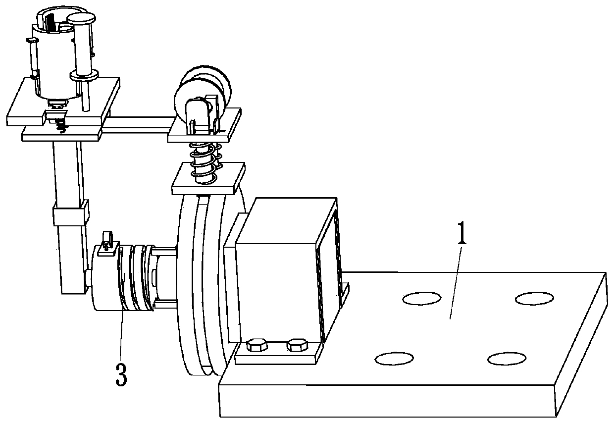
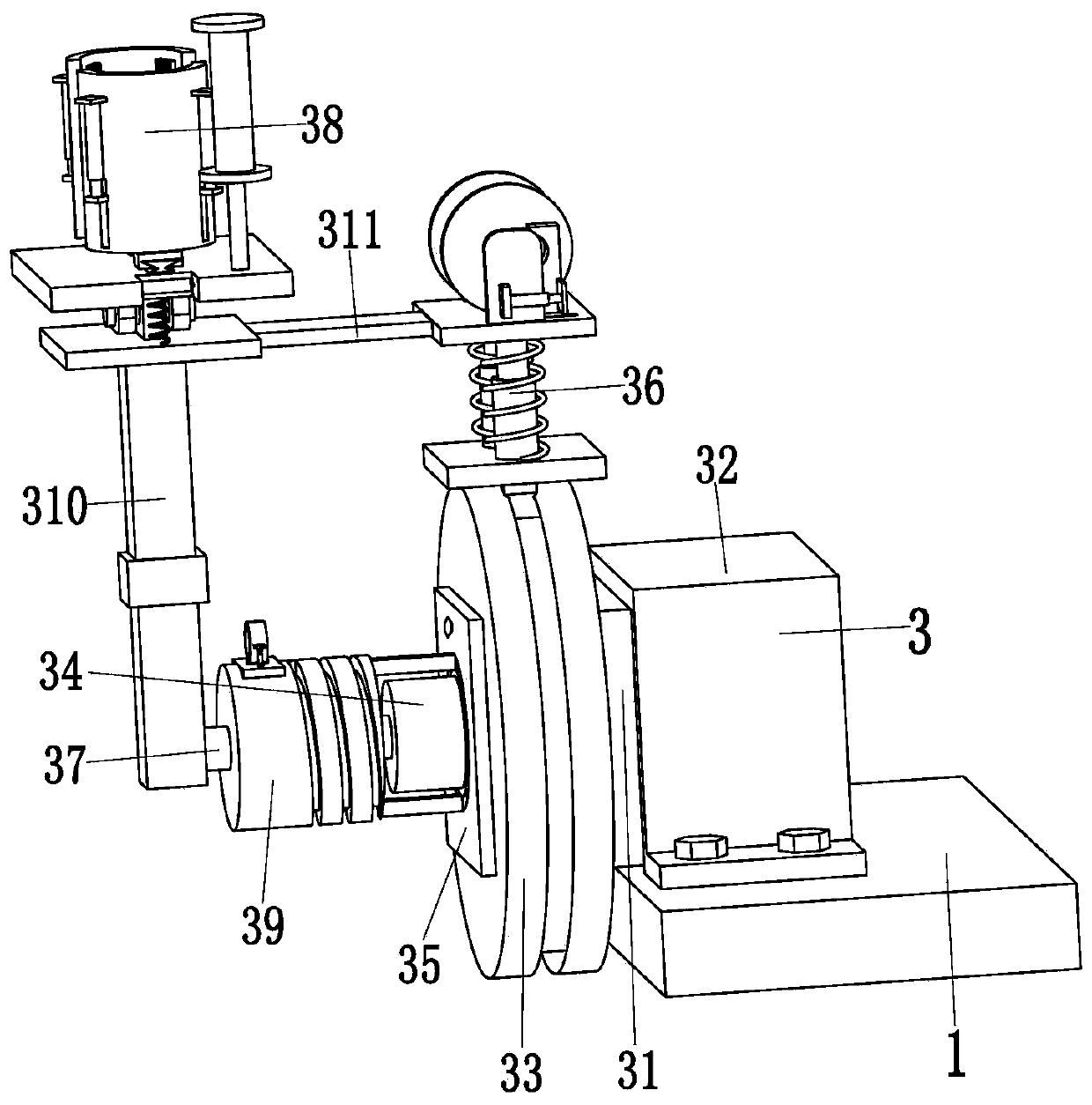
[0028] Such as Figure 1 to Figure 7 As shown, a steel pipe automatic rotary spraying system includes a support plate 1 and a spraying device 3, the support plate 1 is uniformly provided with mounting holes, and the present invention is installed on an external mobile device through the mounting holes on the support plate 1 Above, the spraying device 3 is installed on the top of the left end of the support plate 1 .

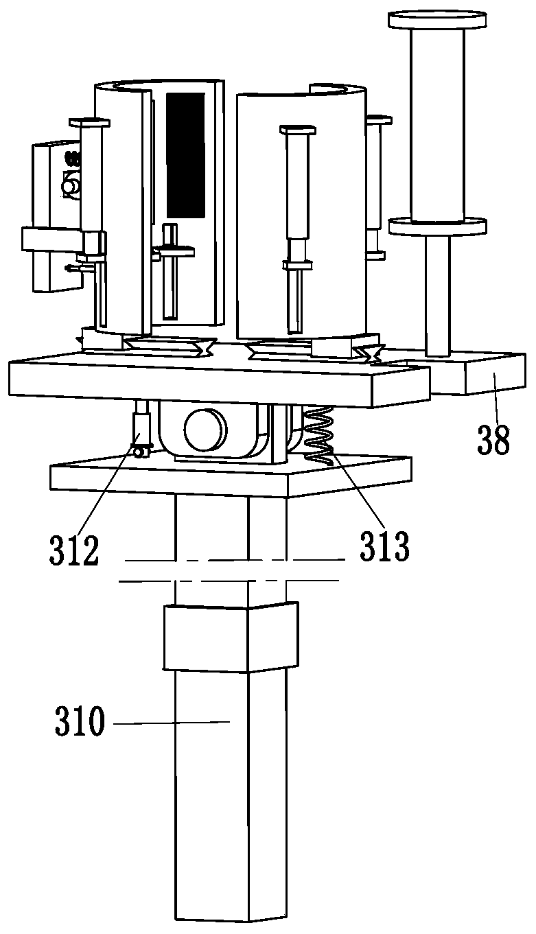
[0029] The spraying device 3 includes an arc spraying machine 31, a fixed frame 32, a rotating frame 33, a rotating motor 34, a rotating pulley 35, a rotating mechanis...


PUM


Abstract

The invention relates to a steel pipe automatic rotating and spraying system and a steel pipe rotating and spraying process. The steel pipe automatic rotating and spraying system comprises a supporting plate and a spraying device; mounting holes are uniformly formed in the supporting plate; through the mounting holes of the supporting plates, the steel pipe automatic rotating and spraying system is mounted on external mobile equipment; the spraying device is mounted at the top of the left end of the supporting plate; and the spraying device comprises an electric arc spraying machine, a fixingframe, a rotating frame, a rotating motor, a rotating connecting plate, a rotating mechanism, a rotating shaft, a clamping mechanism, a guiding mechanism, a rotating telescopic column, a follow-up connecting plate, an angle adjusting rod and a buffering spring. According to the steel pipe automatic rotating and spraying system, difficult problems that a user needs to hold spraying gun to perform spraying operation on an existing blow-off pipe during performing electric arc spraying on the existing blow-off pipe, potential safety hazards are available in manual operation, a spraying gun power supply wire is easy to wind during electric arc spraying, breakage can be caused during spraying a welding wire and so on can be solved.

Description

technical field [0001] The invention relates to the technical field of arc spraying of steel pipes, in particular to an automatic rotating spraying system for steel pipes and a steel pipe rotating spraying process. Background technique [0002] For the sewage pipes with corrosive liquids, steel pipes are generally used. The inner wall of the steel pipes needs to be anti-corrosion arc sprayed, so that the sewage pipes have a long service life. The size of the sewage pipes for corrosive liquids discharged by large factories is relatively large, so that The inner wall of the sewage pipe is usually arc sprayed by manually holding the arc spray gun; the arc spray machine and the spray gun are connected by a power cord, and the power cord at one end of the arc spray machine can be automatically rewound, and the power cord at one end of the arc spray machine is manually pulled , the power cord can be elongated; the back end of the spray gun is connected with a spray welding wire. T...

Claims


Application Information

Patent Timeline
Patent Type & Authority Patents(China)
IPC IPC(8): C23C4/131C23C4/16
Inventor 林瑞
Owner 龙元明筑科技有限责任公司
Learn More