Actuator, optical scanner and image forming device
An actuator and scanner technology, applied in the fields of actuators, optical scanners and image forming devices, can solve problems such as large shape deviation, and achieve the advantages of reducing shape deviation, reducing moment of inertia, and reducing moment of inertia. Effect
- Summary
- Abstract
- Description
- Claims
- Application Information
AI Technical Summary
Problems solved by technology
Method used
Image

Examples
no. 1 approach
[0085] First, a first embodiment of the optical scanner of the present invention will be described.
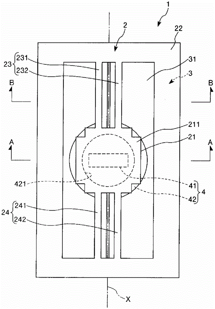
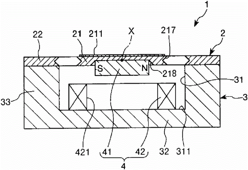
[0086] figure 1 It is a plan view showing the optical scanner (actuator) of the first embodiment of the present invention, figure 2 yes figure 1 The A-A line sectional view in image 3 is for illustration figure 1 A top view of the movable plate provided by the optical scanner shown, Figure 4 yes figure 1 The BB line sectional view in Figure 5 yes Figure 4 A partial enlarged cross-sectional view. Figure 6 is true figure 1 The cross-sectional view illustrating the manufacturing method of the optical scanner is shown, Figure 7 is true figure 1 A cross-sectional view illustrating the fabrication method of the optical scanner is shown. Figure 8 is true figure 1 The cross-sectional view illustrating the manufacturing method of the optical scanner is shown, Figure 9 is for illustration Figure 8 (e) A diagram showing the formation of the connection portion in t...
no. 2 approach
[0259] Next, a second embodiment of the present invention will be described.
[0260] Figure 11 is a plan view showing an optical scanner according to a second embodiment of the present invention, Figure 12 yes Figure 11 Partial enlarged cross-sectional view of line BB in .
[0261] Hereinafter, the optical scanner of the second embodiment will be described focusing on differences from the optical scanner of the above-mentioned embodiment, and descriptions of the same matters will be omitted.
[0262] The optical scanner of the second embodiment is almost the same as the optical scanner 1 of the first embodiment except that the cross-sectional shape of the connecting portion is different. In addition, the same code|symbol is attached|subjected to the same structure as the above-mentioned embodiment.
[0263] Such as Figure 11 As shown, the optical scanner 1A of this embodiment has a base 2A having a vibration system. The base body 2A has a movable plate 21 , a suppor...
no. 3 approach
[0271] Next, a third embodiment of the present invention will be described.
[0272] Figure 13 It is a plan view for explaining the movable plate included in the scanner according to the third embodiment of the present invention.
[0273] Hereinafter, the optical scanner of the third embodiment will be described focusing on differences from the optical scanner of the above-mentioned embodiment, and the description of the same matters will be omitted.
[0274] The optical scanner of the third embodiment is almost the same as the optical scanner 1 of the first embodiment except that the shape of the movable plate in plan view is different. In addition, the same code|symbol is attached|subjected to the same structure as the above-mentioned embodiment.
[0275] Such as Figure 13 As shown, the movable plate 21C included in the optical scanner of this embodiment is composed of a main body 212C, a pair of protrusions 213C, 214C protruding from the main body 212C to both sides in...
PUM
 Abstract
Description
Claims
Application Information