Vertical revolving ring induction type wet-process high-intensity magnetic separator coil

An inductive, strong magnetic separation technology, applied in the direction of coils, magnetic separation, chemical instruments and methods, etc., can solve problems such as coil burnout, copper tube corrosion, and strong magnetic machine paralysis, so as to increase the number of coil turns and solve corrosion problems. problem, the effect of reducing the current

Active Publication Date: 2013-12-11
LONGI MAGNET CO LTD
View PDF7 Cites 2 Cited by
  • Summary
  • Abstract
  • Description
  • Claims
  • Application Information

AI Technical Summary

Problems solved by technology

[0005] The excitation coil is the main core component of the strong magnetic machine. The scaling on the inner wall of the copper tube of the coil will cause the cooling water to flow poorly and the cooling effect will be poor, resulting in a decline in the overall performance of the strong magnetic machine. In severe cases, the coil will be burned, causing the strong magnetic machine to paralysis
Moreover, the corrosion resistance of the copper pipe itself is not very good. If the cooling water contains a little corrosive substances, the copper pipe will be corroded and damaged.

Method used


Image

  • Vertical revolving ring induction type wet-process high-intensity magnetic separator coil
  • Vertical revolving ring induction type wet-process high-intensity magnetic separator coil
  • Vertical revolving ring induction type wet-process high-intensity magnetic separator coil

Examples


Embodiment Construction

[0022] The following will clearly and completely describe the technical solutions in the embodiments of the present invention with reference to the accompanying drawings in the embodiments of the present invention. Obviously, the described examples are only some, not all, embodiments of the present invention. Based on the embodiments of the present invention, all other embodiments obtained by persons of ordinary skill in the art without making creative efforts belong to the protection scope of the present invention.

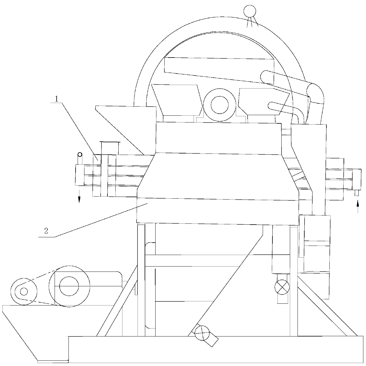
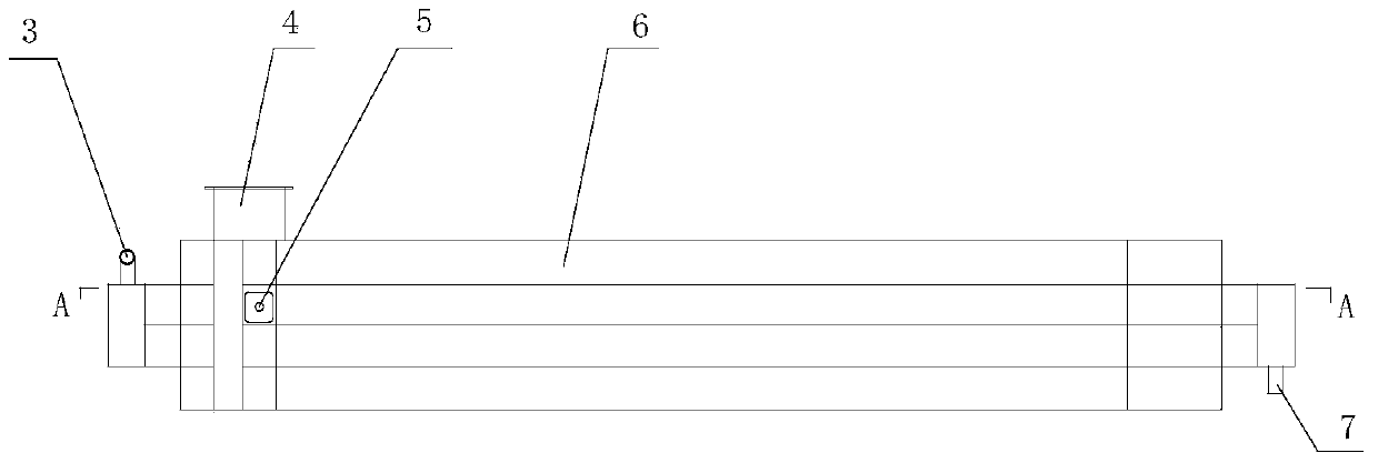
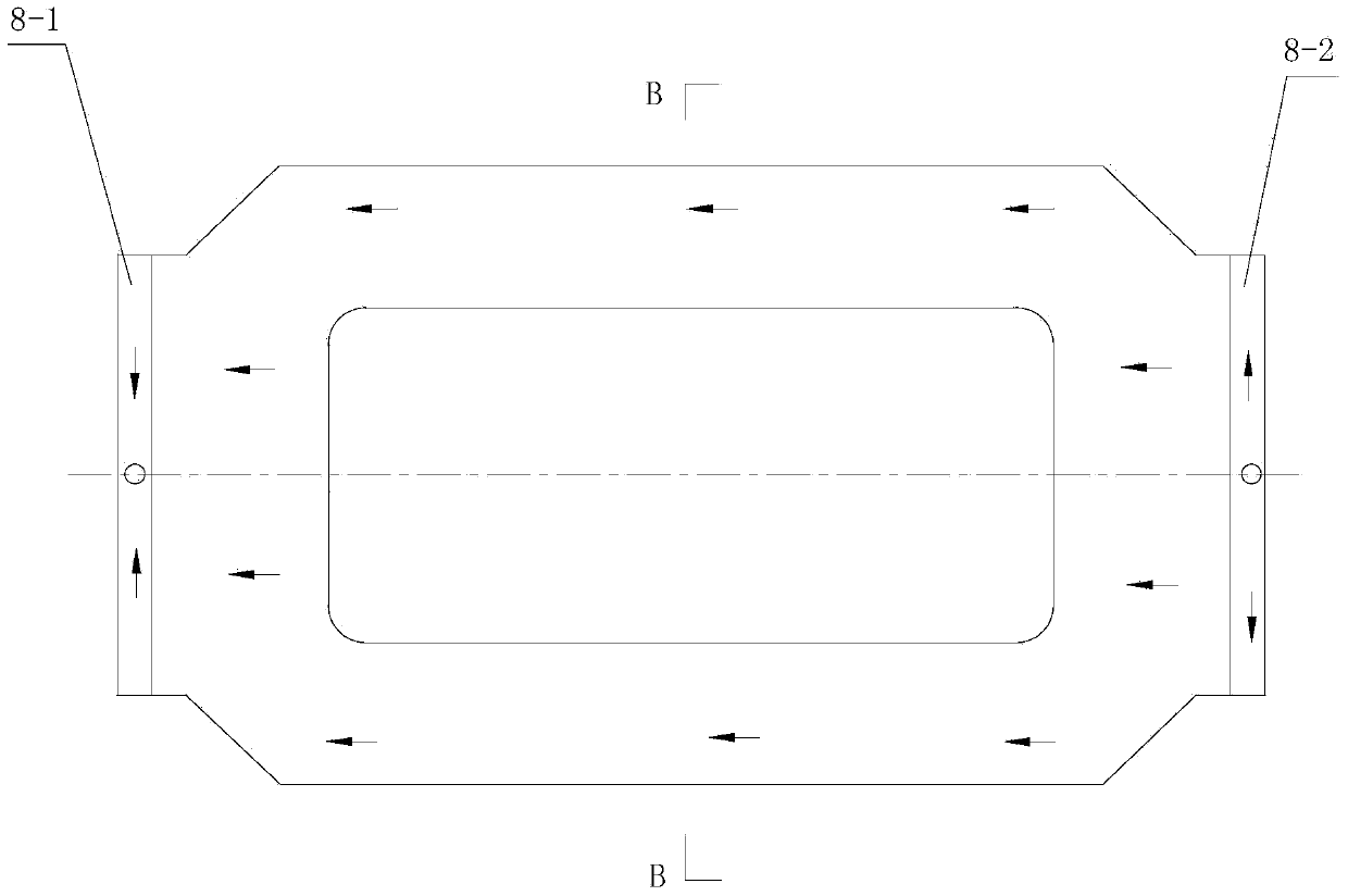
[0023] The core of the coil of the vertical swivel induction wet strong magnetic separator provided by the present invention is that the large water section of the excitation coil and the cooling method of the short water flow process better solve the heat dissipation problem of the coil and have strong heat dissipation Ability to keep the coil working at a lower temperature, so as to achieve the purpose of obtaining a higher magnetic field for the strong magnetic...


PUM


Abstract

The invention discloses a vertical revolving ring induction type wet-process high-intensity magnetic separator coil which is of a multi-layer coil structure and comprises a water outlet (3), a wiring part (4), single disc coils (6), a water inlet (7), a first-end water distribution cavity (8-1), a second-end water distribution cavity (8-2), cooling water channels (11) and water channel retainer rings (12). The vertical revolving ring induction type wet-process high-intensity magnetic separator coil is characterized in that the multiple layers of single disc coils (6) are sequentially arranged from top to bottom along the outer edges and the inner edges of the single disc coils (6) and are welded together; each water channel retainer ring (12) is arranged between the corresponding two adjacent layers of single disc coils (6) to form a gap through which cooling water passes, and is welded on the outer edges and the inner edges of the corresponding two adjacent layers of single disc coils (6), each two adjacent layers of single disc coils (6) are connected to form one body, and the gaps, through which cooling water passes, are taken as the cooling water channels (11). The cooling mode with a large water channel section and a short water channel flow path of the magnet exciting coil can be used for solving the problem of poor heat dissipation of a conventional coil, and the coil can work at low temperature due to strong heat dissipation potential, so that a high-intensity magnetic separator can have a high magnetic field, and the economic benefit and the working efficiency are improved.

Description

technical field [0001] The invention belongs to the technical field of magnetic separation equipment for mines, and in particular relates to a coil of a vertical swivel induction type wet-process strong magnetic separation machine. Background technique [0002] The strong magnetic separator is a kind of beneficiation equipment for the wet enrichment of weak magnetic minerals and the removal of impurities and iron for non-magnetic minerals. The excitation coil is one of the main components of the strong magnetic separator. The high magnetic field generated by the excitation coil enables the strong magnetic separator to achieve the purpose of separating weak magnetic minerals. [0003] Since the 1970s, the excitation coils are all made of copper tubes, that is, the copper tube body is used as a wire to pass current, and the water in the tube is used to cool the coil that is heated due to energization. However, the space utilization rate of this structure is not good, no matte...

Claims


Application Information

Patent Timeline
IPC IPC(8): B03C1/02H01F5/00
Inventor 张承臣唐奇杨娇吴琼马越吴永博
Owner LONGI MAGNET CO LTD
Why Eureka
Try Eureka