
Hobbing die with automatic locking

An automatic locking and gear hobbing die technology, applied in the field of gear hobbing die, can solve the problems of affecting product quality, high labor intensity of manually rotating screw shanks, and the inability of workpiece and worktable to rotate synchronously, so as to achieve the effect of reducing labor intensity.

Active Publication Date: 2016-12-28
ANHUI HELI CO LTD
View PDF6 Cites 0 Cited by
  • Summary
  • Abstract
  • Description
  • Claims
  • Application Information

AI Technical Summary

Problems solved by technology

When the hobbing die is fastened to the workpiece, it is necessary to manually rotate the screw handle through the handle. The screw handle pulls the mandrel to move downward, and the mandrel drives the plug to move downward. The steel ball squeezes the inner wall of the workpiece until the workpiece is locked with the hobbing die; the loosening process is opposite to the locking method, and the manual rotation of the screw handle is labor-intensive during use, and once the screw handle cannot be completely locked, the workpiece and the workbench will not be able to Synchronous rotation, affecting product quality

Method used


Image

  • Hobbing die with automatic locking
  • Hobbing die with automatic locking
  • Hobbing die with automatic locking

Examples


Embodiment Construction

[0013] The present invention will be further described below in conjunction with accompanying drawing:

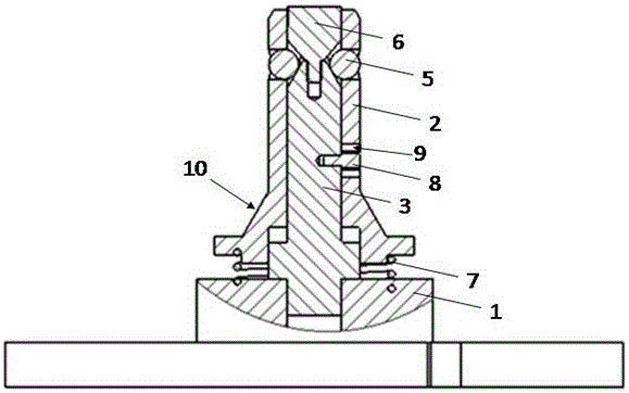
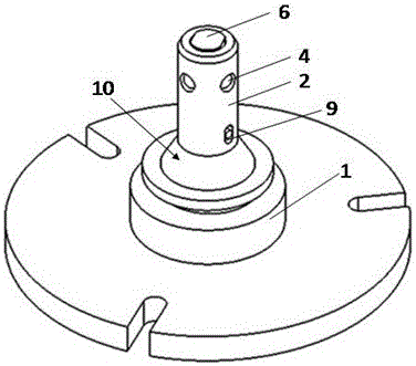
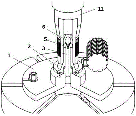
[0014] Such as figure 1 , figure 2 , image 3 A hobbing mold that can be automatically locked as shown includes a mold base 1 and a mold body 2 arranged above the mold base 1. A mandrel 3 is vertically provided on the mold base 1, and a hole 4 is provided on the mold body 2. A steel ball 5 is provided in the hole 4, a plug 6 is provided at the upper end of the mandrel 3, and the mold body 2 is sleeved on the mandrel 3 and the top 6. The characteristic is that the mandrel 3 is fixedly connected with the mold base 1, and the mandrel The upper end of 3 is provided with a conical surface matched with the steel ball 5, and a return spring 7 is provided between the mold body 2 and the mold base 1, and the mold body 2 can only move up and down along the axial direction of the mandrel 3.

[0015] Furthermore, one end of the return spring 7 is fixed to the lower end surface of t...


PUM


Abstract

The invention relates to a hobbing die capable of locking automatically. The hobbing die comprises a die holder and a die body arranged on the die holder. A central spindle is perpendicularly arranged on the die holder. The die body is provided with a hole, and a steel ball is arranged in the hole. The upper end of the central spindle is provided with an ejector head. The central spindle and the ejector head are sleeved with the die body. The central spindle is fixedly connected with the die holder. The upper end of the central spindle is provided with a conical surface matched with the steel ball. A return spring is arranged between the die body and the die holder, and the die body only can move vertically in the axial direction of the central spindle. According to the technical scheme, after a workpiece is placed in the hobbing die, the die body moves downward along with the workpiece, the return spring is compressed at the time till the steel ball a on the die body makes contact with the conical surface at the upper end of the central spindle, and the conical surface of the central spindle extrudes the steel ball to force the workpiece to stop moving downward; after a machine tool tailstock ejector pin applies supporting force downward, the acting force in the direction of the conical surface of the central spindle is applied to the steel ball so that the workpiece and the hobbing die can be completely fixed to realize automatic locking, and therefore labor intensity is lowered for workers.

Description

technical field [0001] The invention relates to a gear hobbing die, in particular to an automatic locking gear hobbing die. Background technique [0002] The hobbing die is a tool used to realize the connection between the workpiece and the worktable. The workpiece is placed vertically, the lower end is positioned and fixed by the hobbing die, and the upper end is positioned by the thimble of the tailstock of the machine tool. Processing of splines. The hobbing die is mainly composed of die base, die body, screw handle, mandrel, end cover, anti-rotation screw, plug and steel ball. When the hobbing die is fastened to the workpiece, it is necessary to manually rotate the screw handle through the handle. The screw handle pulls the mandrel to move downward, and the mandrel drives the plug to move downward. The steel ball squeezes the inner wall of the workpiece until the workpiece is locked with the hobbing die; the loosening process is opposite to the locking method, and the ...

Claims


Application Information

Patent Timeline
Patent Type & Authority Patents(China)
IPC IPC(8): B23Q3/06
Inventor 袁兵昌姚奇
Owner ANHUI HELI CO LTD
Learn More