A device for collecting condensate on the inner wall of wet flue gas flue

A collection device and technology in the flue, which is applied in the exhaust gas device, combustion product treatment, combustion method, etc., can solve the situation that the inner wall of the flue is easy to condense, and does not have the function of collecting condensate on the inner wall of the wet flue. and other problems to achieve the effect of avoiding re-accumulation, simple structure and easy implementation

Active Publication Date: 2015-08-26
SHANGHAI DEFOG ENVIRONMENTAL SCI & TECH
View PDF6 Cites 0 Cited by
  • Summary
  • Abstract
  • Description
  • Claims
  • Application Information

AI Technical Summary

Problems solved by technology

[0012] At present, most of the conventional wet flue structures do not consider the easy condensation on the inner wall of the flue, and do not have the function of collecting condensate on the inner wall of the wet flue.

Method used


Image

  • A device for collecting condensate on the inner wall of wet flue gas flue
  • A device for collecting condensate on the inner wall of wet flue gas flue
  • A device for collecting condensate on the inner wall of wet flue gas flue

Examples


Embodiment 1

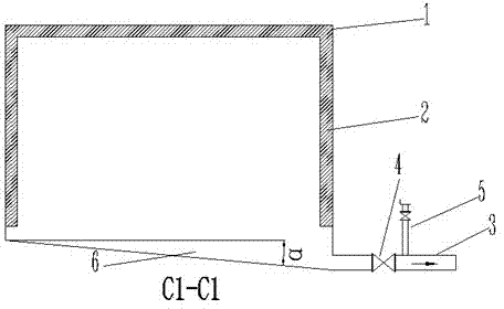
[0048] refer to Figure 1-5 A device for collecting condensate on the inner wall of a wet flue gas flue provided by the present invention is used in a flue with a rectangular cross-section, and includes at least one set of collection structures. Several collection structures are arranged on the inner wall of the flue The condensate on the wall is discharged from the flue, wherein the collection structure includes a collection tank 2 , a drainage tank 6 , a guide pipe 3 , a drain valve 4 and a flush valve 5 .

[0049] Specifically, such as image 3 As shown, the collection tank 2 is fixedly arranged on the top and both sides of the inner wall of the rectangular flue 1 by means of riveting, welding or bonding, and the direction of the notch of the collection tank 2 is opposite to the flow direction of the flue gas in the flue, so that The condensate on the inner wall of the flue 1 passes through the collection tank 2 when moving forward along the inner wall of the flue 1 under ...

Embodiment 2

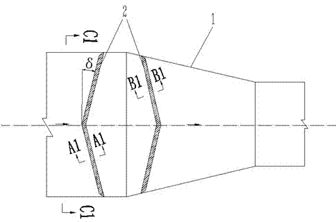
[0056] refer to Figure 6-9 In this embodiment, the device for collecting condensate on the inner wall of the wet flue gas flue is used in the circular flue, including at least one set of collection structures, and several collection structures are arranged on the inner wall of the circular flue The condensate is discharged from the flue. Wherein, the collection structure includes a collection tank 2 , a drainage tank 6 , a guide pipe 3 , a drain valve 4 and a flushing valve 5 .

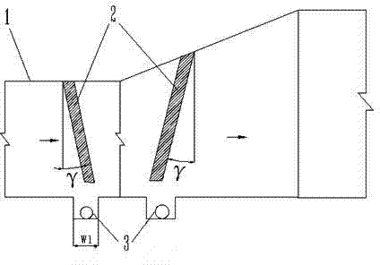
[0057] Such as Figure 6-7 As shown, the collection tank 2 is fixedly arranged along the top of the circular flue 1 and the inner walls of the left and right sides, the collection tank 2 and the radial direction of the flue 1 are inclined at an angle γ, and the inclination direction of the collection tank 2 is in line with the inside of the flue 1. The flow direction of the flue gas is the same, and the range of the included angle γ is 10°≤γ≤20°, preferably 15°; in this embodiment, as Figure 8 As...


PUM


Abstract

The invention provides a wet flue gas flue inner wall condensed liquid collecting device which comprises a plurality of collecting structures. The collecting structures are arranged on the inner wall of a flue, and each collecting structure comprises collecting grooves which are formed in the top and the two sides of the inner wall of the flue, a water draining groove which is formed in the bottom of the flue, a flow guide tube which is connected with the outer portion of the water draining groove, a liquid draining valve which is arranged on the water draining groove and a flushing valve which is arranged on the flow guide tube. The cross section of each collecting groove is of an L shape, the direction of a groove opening of each collecting groove is opposite to the flowing direction of flue gas, the collecting grooves and the radial direction of the flue tilt in a certain degree, and the tilting direction is the same as the flowing direction of the flue gas. The wet flue gas flue inner wall condensed liquid collecting device is simple in structure, wide in application range, low in energy consumption, low in failure rate, good in using effect, safe, reliable, economical, practical, and easy to implement. In addition, the wet flue gas flue inner wall condensed liquid collecting device can discharge condensed liquid timely, and the condensed liquid is prevented from being carried secondarily after being collected.

Description

technical field [0001] The invention relates to the technical field of design inside a wet flue gas flue, in particular to a device for collecting condensate on the inner wall of a wet flue gas flue. Background technique [0002] The limestone-gypsum wet flue gas desulfurization process is the most widely used and mature process in the world today, and it is also the leading process for desulfurization of domestic thermal power plants. More than 90% of thermal power units above 300MW in my country adopt limestone-gypsum wet flue gas desulfurization (WFGD) technology. Desulfurization Design Technical Regulations (DL / T5196-2004) stipulates that "under design conditions, the flue gas temperature at the chimney inlet after desulfurization should generally reach 80°C or higher for discharge", so the WFGD systems installed in the early stage are basically equipped with flue gas heat exchange Device (Gas-Gas Heater, GGH). However, in actual operation, serious corrosion of GGH compo...

Claims


Application Information

Patent Timeline
Patent Type & Authority Patents(China)
IPC IPC(8): F23J13/00
Inventor 戴永阳靳庆新赵江明
Owner SHANGHAI DEFOG ENVIRONMENTAL SCI & TECH
Why Eureka
Try Eureka