Method for stably erecting and accurately aiming at horn antenna and triangular support for measurement

A technology of horn antenna and triangular bracket, which is applied in the direction of antenna support/installation device, folding antenna, etc.

Inactive Publication Date: 2013-12-11
UNIT 63892 OF PLA
View PDF6 Cites 6 Cited by
  • Summary
  • Abstract
  • Description
  • Claims
  • Application Information

AI Technical Summary

Problems solved by technology

[0004] At present, since the commonly used horn antenna is connected to the general antenna bracket by only one base screw, when the horn antenna with a lower frequency band is erected, the antenna weighs ten A few kilograms or even dozens of kilograms, resulting in unstable connection between the antenna and the antenna stand
[0005] During the field test, in order to ensure the communication between the microwave signal source and the receiving antenna, the receiving antenna needs to be erected on the top of the mountain or on the test tower, and the wind is often relatively strong. If you are not careful, the test antenna stand will fall and the antenna will be damaged

Method used


Image

  • Method for stably erecting and accurately aiming at horn antenna and triangular support for measurement
  • Method for stably erecting and accurately aiming at horn antenna and triangular support for measurement
  • Method for stably erecting and accurately aiming at horn antenna and triangular support for measurement

Examples


Embodiment Construction

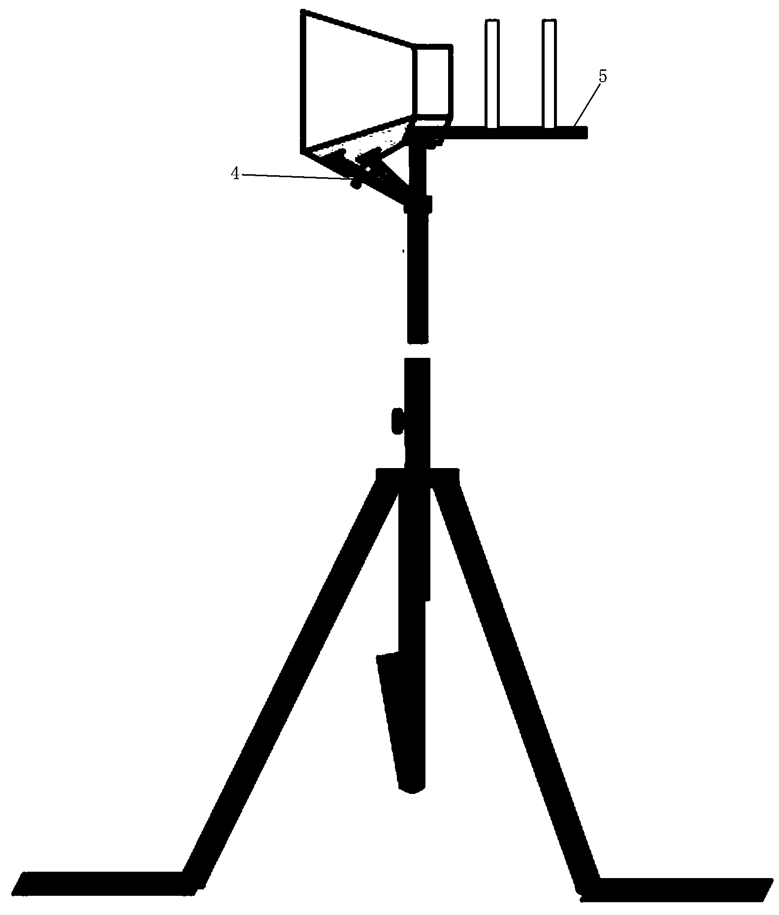
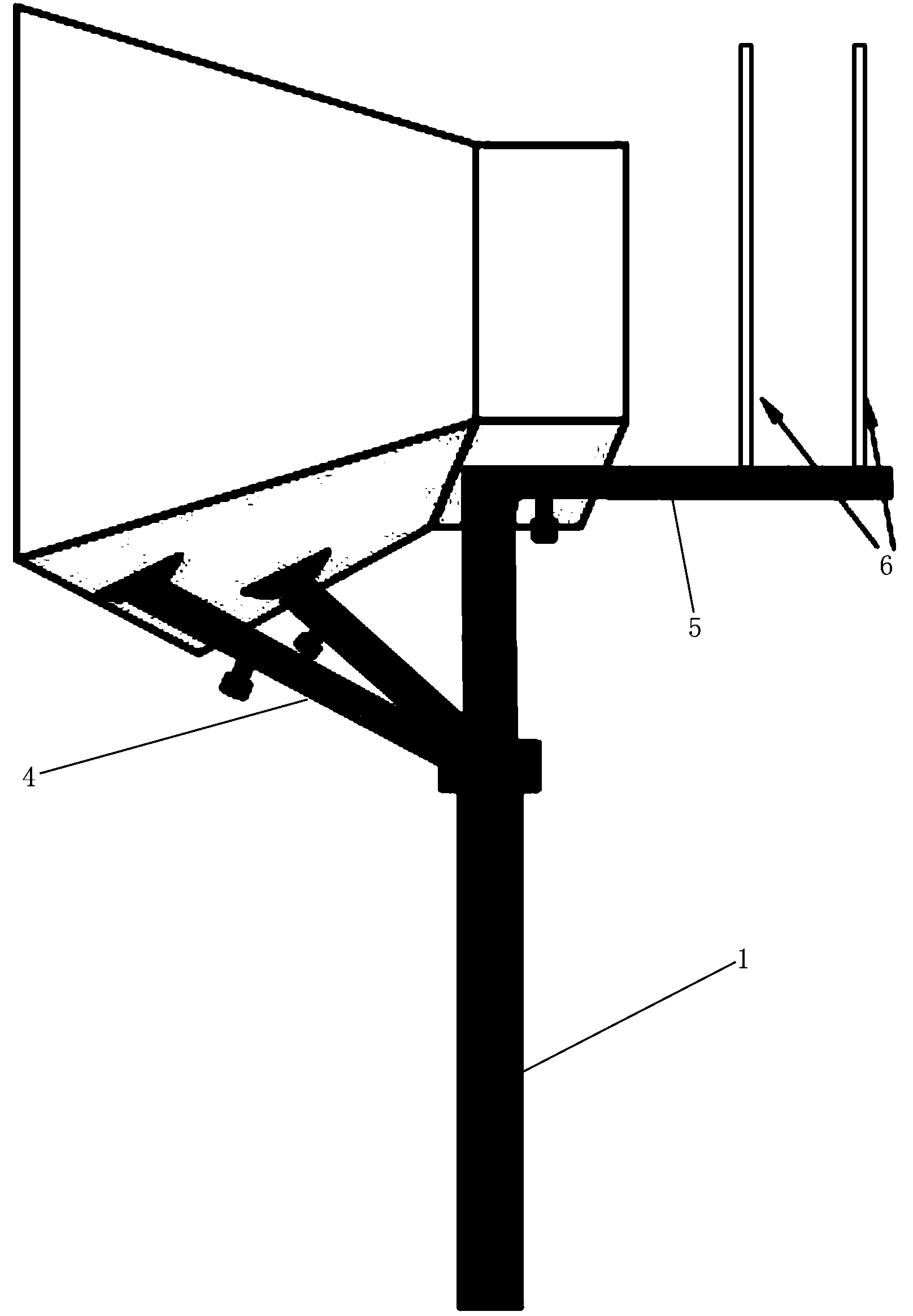
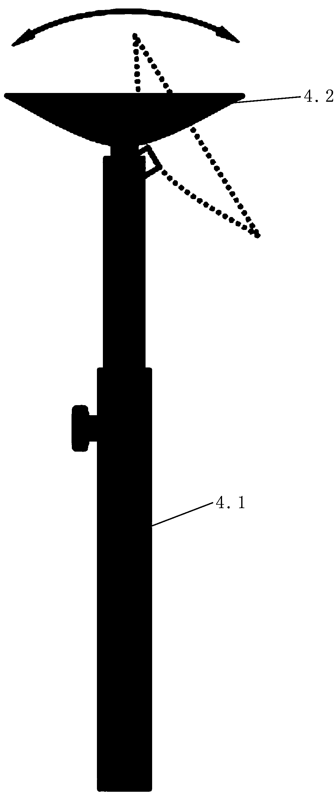
[0035] like figure 1 , 2 , shown in 3, 4, 5, a kind of triangular bracket for stably erecting and accurately aiming at the horn antenna for testing includes: antenna top bracket 1, antenna bracket sleeve 2, foldable antenna counterweight frame 3; described antenna top casing The bracket 1 provides the connection between the antenna bracket sleeve 2 and the foldable antenna counterweight frame 3; the antenna top bracket 1 is provided with a horn antenna three-point fixing bracket for fixing the horn antenna, and the horn antenna three-point fixing bracket is supported by two inclined The telescopic support arm 4 and a horizontal main support arm 5 are formed; the telescopic support arm 4 is formed by connecting the telescoping rod 4.1 and the sucker 4.2 rotating at 180°; the main support arm 5 is provided with a central point scale 6; The main support arm 5 with the center point scale is provided with a front and rear sight 7 for fast and accurate alignment of the receiving a...


PUM


Abstract

The invention relates to the technical field of antenna stabilizing equipment, and discloses a method for stably erecting and accurately aiming at a horn antenna and a triangular support for measurement. The triangular support comprises an antenna top support body, an antenna support sleeve and a foldable antenna weight rack. The antenna top casing support body is connected with the foldable antenna weight rack through the antenna support sleeve. A horn antenna three-point fixing supporting frame which is arranged on the antenna top support body is composed of two inclined telescopic supporting arms and a horizontal main supporting arm. Each telescopic supporting arm is connected by a telescopic rod and a sucking disc which can be rotated by 180 degrees. A receiving antenna and a front-and-back sighting device are arranged on the main supporting arm, wherein the front-and-back sighting device is rapidly and accurately aligned to a microwave signal source. According to the method and the triangular support, the receiving antenna can quickly aim at the microwave signal radiation source, and then the power of received signals is maximum; the horn antenna and the triangular support are stably combined; counter weight is added on the antenna weight rack, and therefore the antenna triangular support is stably fixed on the ground.

Description

[0001] 【Technical field】 [0002] The invention relates to the technical field of antenna stabilizing equipment, in particular to a method for stably erecting and precisely aiming at a horn antenna and a tripod for testing. [0003] 【Background technique】 [0004] At present, when using the horn antenna for various tests, it is necessary to precisely aim the receiving antenna at the transmitting antenna to ensure the maximum received power. In actual test engineering, it is a very time-consuming task to accurately align the receiving antenna with the microwave signal emission source. , especially when the transmitting antenna is far from the receiving antenna. [0005] When using the standard horn antenna to test the receiving power from 0.77GHz to 40GHz, 10 pairs of standard horn antennas are required. The antenna type and frequency test range are as follows: TX-9BZ15.5 standard antenna, frequency band 0.77~1.15GHz; TX-14BZ15. 5 standard antenna, frequency band 1.13~1.73GH...

Claims


Application Information

Patent Timeline
Patent Type & Authority Applications(China)
IPC IPC(8): H01Q1/12H01Q1/08
Inventor 杨会民朱震陈珺卜云萍王道酉王毅李平
Owner UNIT 63892 OF PLA
Why Eureka
Try Eureka