Overhead line cross wiring device

A technology for overhead lines and suspension wires, applied in the direction of overhead lines/cable equipment, etc., which can solve the problems of being unsuitable for long-distance construction and erecting wires, and having large use limitations

Active Publication Date: 2013-12-11
STATE GRID CORP OF CHINA +1
View PDF5 Cites 21 Cited by
  • Summary
  • Abstract
  • Description
  • Claims
  • Application Information

AI Technical Summary

Problems solved by technology

When the wire crosses the optical cable, it can effectively protect the optical cable and the overhead wire from damage, but the above-mentioned 10KV di

Method used


Image

  • Overhead line cross wiring device
  • Overhead line cross wiring device
  • Overhead line cross wiring device

Examples


specific Embodiment 1

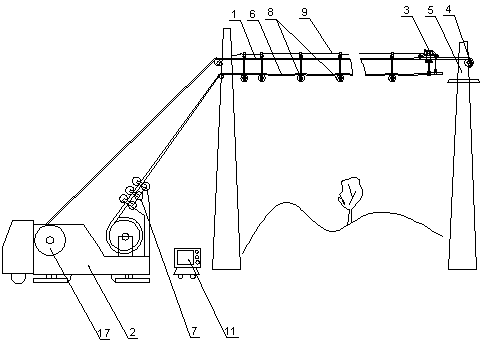
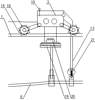
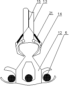
[0020] like figure 1 , 2 and image 3 As shown, an overhead line spanning wire laying device includes an overhead suspension wire 1, a pay-off vehicle 2, a traction block 3 with a driving mechanism, and a suspension wire pulley. On the fixed object 5 in front of the object, the traction block 3 pulls the wire 6 to be laid to move on the elevated suspension wire 1, and the suspended wire supporting wheel supports the wire 6 and hangs it on the elevated suspension wire 1. 2 wire anti-twisting devices 7 are arranged at the outlet end.

[0021] The suspended wire support wheel includes several groups of pulleys 8, and stay wires 9 are arranged between the pulleys 8, wherein the frontmost pulley 8 is connected to the traction block 3.

[0022] The driving mechanism includes a driving motor and a signal transceiver 10 , the driving motor is electrically connected to a power supply unit 20 through a storage device, and the signal transceiver 10 is wirelessly connected to a ground ...

specific Embodiment 2

[0029] A cross-laying device for overhead lines, which differs from the first embodiment in that: one overhead suspension wire 1 is provided.

specific Embodiment 3

[0030] A device for laying wires across an overhead line, the difference from the specific embodiment 1 or 2 is that: the fixed object 5 is provided with a traction mechanism connected to the traction block 3, and the traction mechanism is driven by a remote-controlled stepping motor .

[0031]In the above-mentioned embodiment, the present invention first erects the overhead suspension wire that crosses the obstacle, installs the traction block, clamps the wire to be laid, and sets the hull or three wire lifting rods under the traction block, so that multiple wires can be connected at the same time. Forward, the traction trolley realizes that the traction trolley pulls the laid wires to move on the elevated suspension wire through its own driving mechanism. root, the lower part of the traction block is equipped with a counterweight balancer to ensure the smooth movement of the traction block and prevent the rollover from being out of control. The movement gradually pulls away...


PUM


Abstract

The invention discloses an overhead line cross wiring device which comprises an overhead suspension wire, a wire barrow, a traction tackle with a drive mechanism, and suspension wire supporting wheels, wherein the front end of the overhead suspension wire is connected to a fixed object in front of a crossing object through a tensioning mechanism, the traction tackle pulls wires to be laid to move on the overhead suspension wire, the suspension wire supporting wheels support the wires and are suspended on the overhead suspension wire, a wire anti-twisting device is arranged at the outgoing line end of the wire barrow, and the lower portion of the traction tackle is provided with a counterweight balancer. According to the overhead line cross wiring device, firstly, the overhead suspension wire is erected, the traction tackle is installed to pull the wires to be laid to move on the overhead suspension wire, advancing of the wires is prevented from being affected by overlarge droop through the suspension wire supporting wheels, the counterweight balancer is utilized to ensure stable movement of the traction tackle, remote cross stringing is achieved conveniently, meanwhile, abrasion between the wires and the ground does not exist, the stringing quality is superior, and the overhead line cross wiring device is suitable for not only line laying but also line repairing, and has high degree of automation.

Description

technical field [0001] The invention belongs to the technical field of wiring of overhead transmission lines in electric power systems, and in particular relates to a cross-laying device for overhead lines. Background technique [0002] Overhead lines, such as power overhead lines, often require various spanning erections. Due to the limitations of the height, width, and geographical location of the spanned objects, the spanning operation is complicated, the workload and difficulty are large, and the power outage time is long. For the erection across the line, there are many methods used in the prior art: landing is crossed over the lower line, or setting up the over-the-line frame. However, in the way of landing lines, the phenomenon of line damage and torsion and loose strands is serious, and repeated climbing and wiring are required, which is not only labor-intensive, but also poor in safety. The geographical location is limited, the workload is heavy, the cumulative er...

Claims


Application Information

Patent Timeline
IPC IPC(8): H02G1/04
CPCH02G1/04
Inventor 张洪涛韩爱芝刘守明史宏伟张洋
Owner STATE GRID CORP OF CHINA
Why Eureka
Try Eureka