Reflection layer system for solar applications and method for the production thereof

A reflective layer and solar energy technology, which is applied in the field of reflective layer systems, can solve the problems of increased material consumption, inability to use multiple applications, high material costs, etc., and achieve the effects of cost saving, material saving, and strong adhesiveness

A reflective layer and solar energy technology, which is applied in the field of reflective layer systems, can solve the problems of increased material consumption, inability to use multiple applications, high material costs, etc., and achieve the effects of cost saving, material saving, and strong adhesiveness

CN103443559AInactive Publication Date: 2013-12-11VON ARDENNE ANLAGENTECHNIK GMBH

Image

  • Reflection layer system for solar applications and method for the production thereof
  • Reflection layer system for solar applications and method for the production thereof
  • Reflection layer system for solar applications and method for the production thereof

Examples


Embodiment Construction

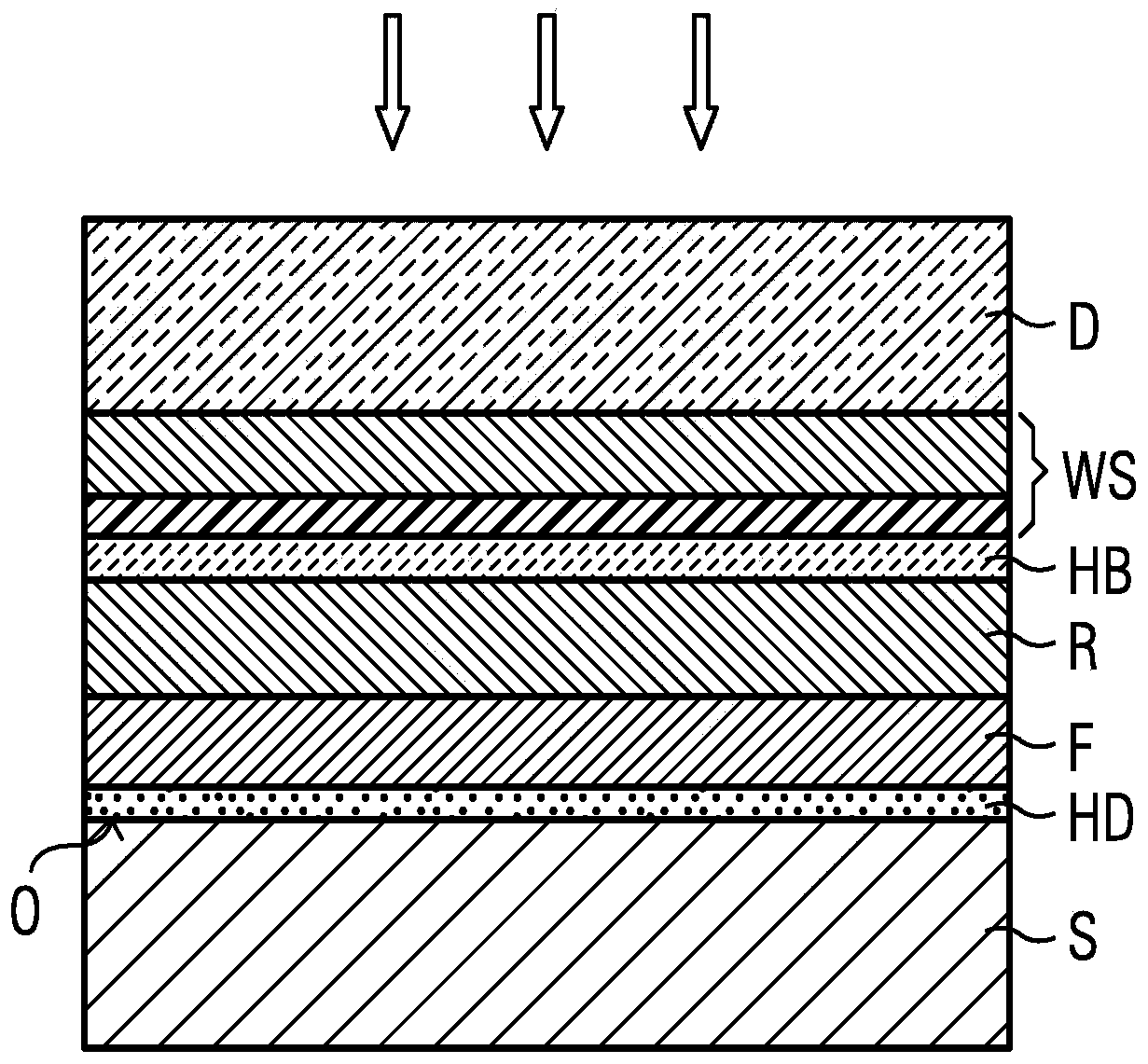
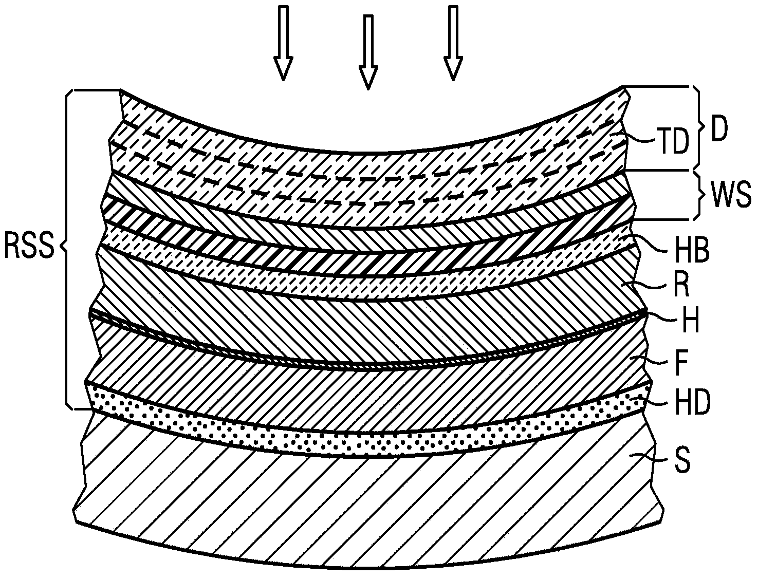
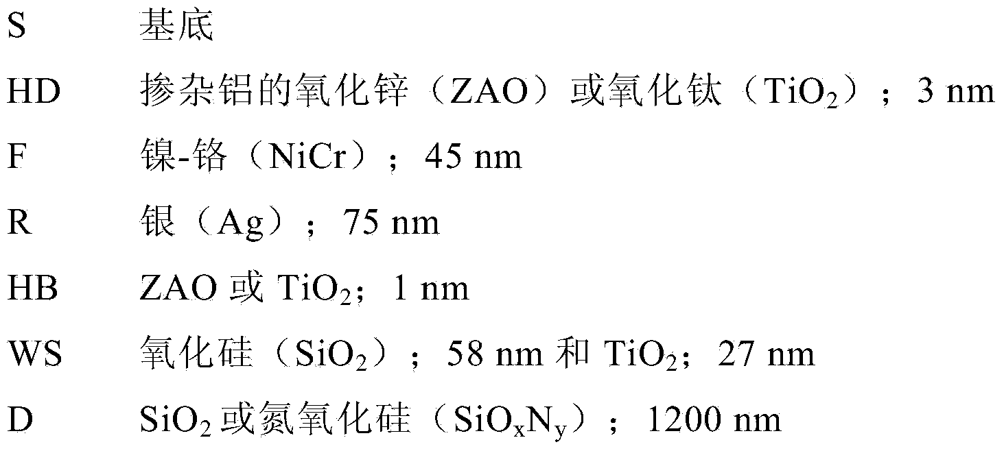
[0043] in accordance with figure 1 In an embodiment, the reflective layer system according to the invention has the following layer structure, which, viewed from the substrate upwards, has the layer thicknesses described below in the direction of light incidence (identified by the arrow):

[0044]

[0045] According to ISO 9050:2003, a total solar reflection of greater than 96% is obtained with such a front side mirror reflector system.

[0046] To produce the layer system, the layers are successively deposited by magnetron sputtering on a correspondingly carefully polished, washed and dried substrate S, for example float glass. Alternatively, a combination of magnetron sputtering with other PVD methods such as e-beam evaporation, or CVD or PECVD methods or another wet chemical coating method is also feasible.

[0047] The substrate S may optionally be subjected to a plasma pretreatment in vacuum prior to coating by sputtering. For this purpose, for example, the 2-5 x 10 ...


PUM

PropertyMeasurementUnit
thicknessaaaaaaaaaa
thicknessaaaaaaaaaa
thicknessaaaaaaaaaa

Abstract

The invention relates to a reflection layer system RSS and to a method for the production thereof for front-surface mirrors for solar applications, comprising a layer that is highly reflective in the solar spectrum on a substrate S. In order to achieve such a reflection layer system RSS on curved and flat substrates S while keeping the use of material low and obtaining higher TSR values, deposited on the substrate S are a metallic, reflective functional layer F, a metallic reflective layer R, and a transparent, dielectric protective layer as a top layer D, which contains an oxide, nitride or oxynitride of a metal or semiconductor and the thickness of which is 500 nm or more, preferably more than 1 [mu]m.

Description

technical field [0001] The invention relates to a reflective layer system for front side mirrors for solar applications, having a layer highly reflective in the solar spectrum and deposited on a substrate. The invention also relates to a method for producing a reflective layer system. Background technique [0002] Reflective layer systems have long been used in many areas of our life; however, they are becoming more and more important today, eg for mirrors used to solve energy problems. Whereas mirrors for conventional indoor applications need to reflect "only" the visible part of the spectrum, for solar applications they must reflect as much as possible the entire range of the solar spectrum. [0003] As for the mirrors, depending on which side of the substrate the main reflection takes place, a distinction is generally made here between front-side mirrors and rear-side mirrors. [0004] Reflective layer systems are produced for indoor and outdoor applications such as sol...

Claims


Application Information

Patent Timeline
11 Dec 2013
Publication
CN103443559A
IPC
F24J2/10; F24S23/70
CPC
Y02E10/40; F24S2025/601; F24S23/82; C03C17/36; C03C17/3644; C03C17/3649; C03C17/3663; C03C17/3678
Inventors
克里斯多佛·科克尔特; 马库斯·贝伦特