Rivet inserter

A technology for inserters and anchors, applied in surgical instruments, applications, etc., can solve the problems of easy contact with sutures, pollution, and difficulty in finding thread ends. Fixed and reliable effect

Active Publication Date: 2013-12-18
DABO MEDICAL TECH CO LTD
View PDF6 Cites 6 Cited by
  • Summary
  • Abstract
  • Description
  • Claims
  • Application Information

AI Technical Summary

Problems solved by technology

[0003] But, there is following defect in this anchor inserter: (1), when suture thread is wound on handle, suture thread is exposed outside, and skin easily touches suture thread during doctor's operation, makes it polluted
(2) The winding of the suture thread on the handle is irregular, which can easily cause knotting and threading of the thread ends, and it is difficult to find the thread ends when unthreading; thus causing inconvenience in operation

Method used


Image

  • Rivet inserter
  • Rivet inserter
  • Rivet inserter

Examples


Embodiment Construction

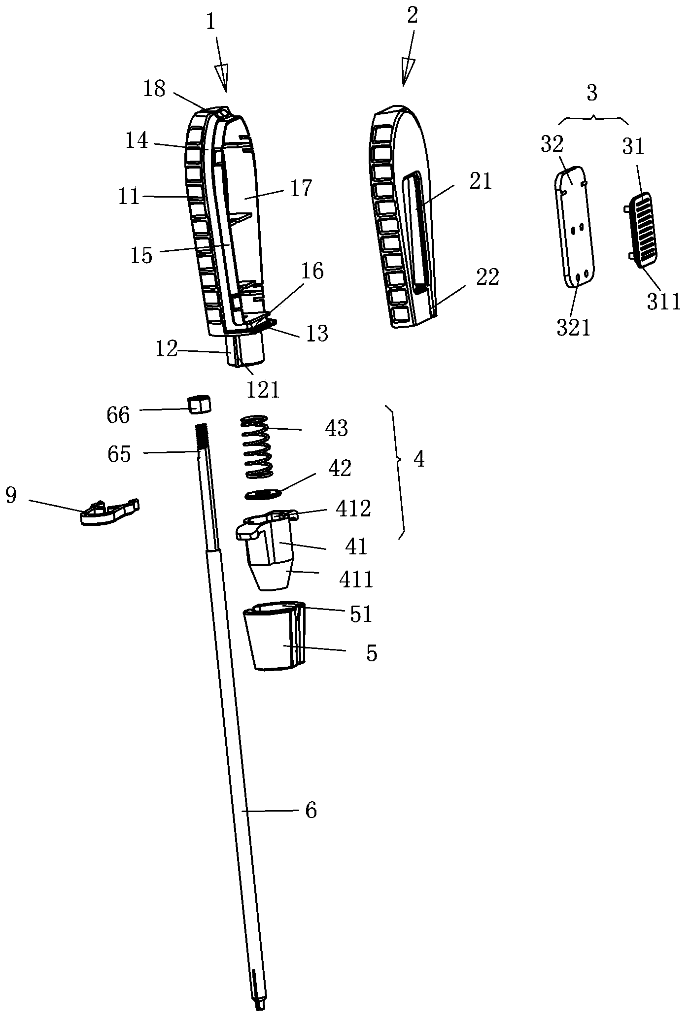
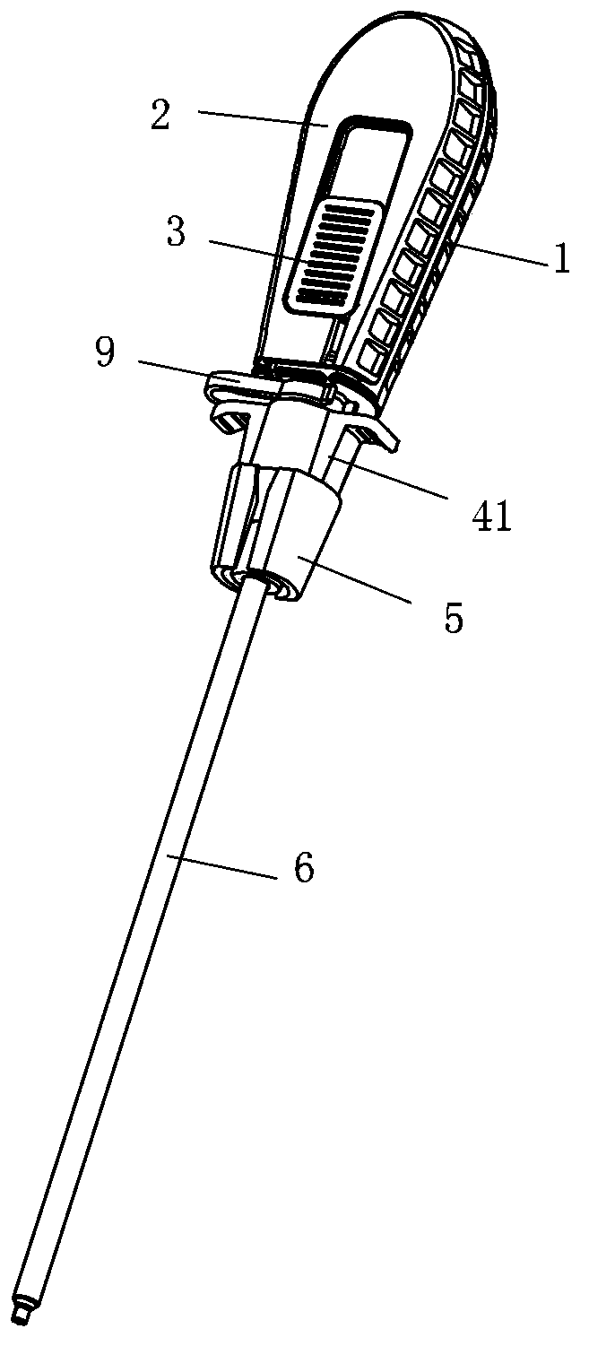
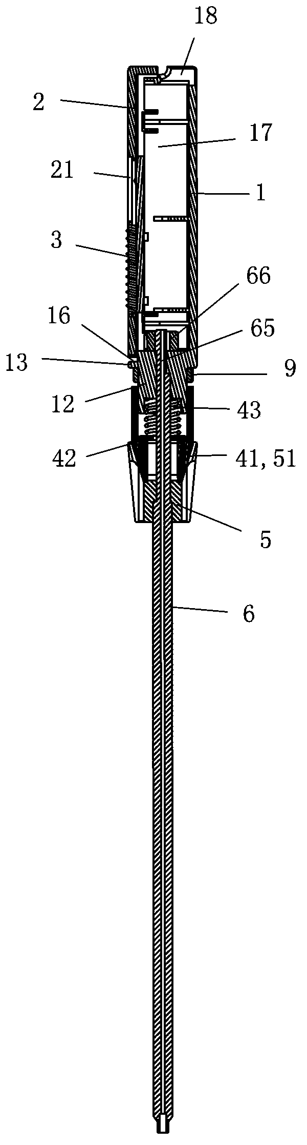
[0025] The structure of an embodiment of the anchor inserter of the present invention, please refer to figure 1 , figure 2 and image 3 . The anchor inserter has a handle, a wire crimping assembly 4, a fixing seat 5, a main rod 6 and a locking clip 9. The handle is composed of a handle main body 1, a handle cover 2 and a push-pull plate 3 ; The crimping assembly 4 is composed of a crimping seat 41 , a gasket 42 and a spring 43 . In the following, the upper part represents the rear in actual application, and the lower part represents the front in actual application.

[0026] The main part of the handle main body 1 is the grip part 11; the grip part 11 is a box body with an open right side, and a baffle 13 is arranged at the lower end, and the center of the lower surface of the baffle 13 extends downward to connect the crimping seat 41 The guide tube 12, the outer periphery of the guide tube 12 is provided with two opposite guide ribs 121, and the two guide ribs 121 are pa...


PUM


Abstract

The invention discloses a rivet inserter and relates to ligament stitching operation auxiliary apparatus. The rivet inserter comprises a thread pressing clamp seat, a spring, a fixing seat, a gripping handle and a main rod. The front end of the main rod is provided with a short circular pipe radially penetrating a cutting groove. The front end of a tubular body of the thread pressing clamp seat forms a conical face, the rear end of the tubular body is provided with a handle, and an inner hole of the tubular body is of step shape with big rear and small front. A fixing seat body is mounted at the rear portion of the main rod, T-shaped fins are disposed on two sides of the fixing seat body, and the rear portion of each T-shaped fin extends out of the fixing seat body and is provided with an inner flange on the inner surface. The front end of the thread pressing clamp seat is inserted into the two fins of the fixing seat. The gripping handle is provided with a recessed closed groove, and a stitching thread can be wound on the groove. A guide tube inserting into the rear section of the inner hole of the thread pressing clamp seat is disposed at the front end of the gripping handle. The part, located behind the fixing seat, of the main rod enters the inner hole of the thread pressing clamp seat, penetrates the spring, and is fixed in the inner hole of the guide tube. Two ends of the spring press the bottom of the rear section of the inner hole of the thread pressing clamp seat and the guide tube to allow the conical face of the thread pressing clamp seat abut against the inner flanges on the inner surface of the two fins of the fixing seat.

Description

technical field [0001] The invention relates to an auxiliary instrument used in ligament suturing operation. Background technique [0002] An anchor is a device that fixes a ligament to a bone during ligament suturing. Its structure is as follows: Figure 10 As shown: the main body of the anchor 7 is a bone screw part 71, and the end of the bone screw part 71 extends upward along the axis with a flat handle 72; The outer surface of each reinforcing rib 721 is two intersecting concave facades; the upper parts of the two narrower facades are respectively provided with wire grooves 723, and the rear end face center of the handle 72 is provided with a wire hole 722, two wire grooves The lower end of 723 is provided with a horizontal through hole connecting the bottom of wire hole 722 . During use, one end of the suture passes through the wire hole 722 and a wire groove 723 to tie a knot, and is fixed on the anchor 7 . Fixing the anchor and ligament to the bone requires the use...

Claims


Application Information

Patent Timeline
Patent Type & Authority Applications(China)
IPC IPC(8): A61B17/04
Inventor 张喜贵
Owner DABO MEDICAL TECH CO LTD
Why Eureka
Try Eureka