Drilling fluid skimming tank
A drilling fluid and oil tank technology, applied in the field of drilling fluid oil skimming tanks, can solve problems such as inability to effectively separate crude oil, achieve the effects of stabilizing fluid and flow state, eliminating or eddy current, and increasing the probability of collision
- Summary
- Abstract
- Description
- Claims
- Application Information
AI Technical Summary
Problems solved by technology
Method used
Image

Examples
Embodiment 1
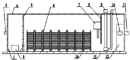
[0037] A drilling fluid skimming tank, comprising a tank body 4, in which an oil inlet bin, a separation bin and a discharge bin are sequentially arranged along the liquid flow direction; the oil inlet bin communicates with the oil inlet provided on the tank body 4, The oil inlet chamber communicates with the separation chamber, the separation chamber communicates with the discharge chamber, and the discharge chamber communicates with the discharge pipe 11 provided on the tank body 4 .
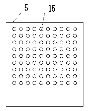
[0038] A preferred embodiment of the present invention is that the oil inlet bin communicates with the oil inlet 3 provided on the tank body 4, and a filter plate 5 is arranged in the oil inlet bin, and holes 15 are evenly distributed on the filter plate 5, and the filter plate The liquid inflow surface of 5 is provided with filter screen, and the oil inlet chamber communicates with the separation chamber through the filter plate 5 . This is a preferred mode, and the structure of the oil inlet...
Embodiment 2
[0046] The present invention includes an oil inlet bin, a separation bin and a discharge bin, the oil inlet bin, the separation bin and the discharge bin are arranged in a tank body 4, the tank body 4 is a rectangular closed structure, and a base 13 is arranged under the tank body 4, The four corners of the base 13 are provided with lugs.
[0047] The oil inlet bin includes: oil inlet 3, filter plate 5, slag discharge door 2 and inclined block 1; the inclined block 1 is arranged around the bottom of the oil inlet bin; the slag discharge door 2 is arranged on the oil inlet bin; the oil inlet 3 It is set in the middle of the front end of the tank, connected with oil nonel, and the outside is connected with the input pipe. The filter plate 5 is arranged between the front end panel of the tank body 4 and the separator 6, and has holes 15 on the filter plate 5 with a plate thickness of 10 cm. network;
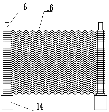
[0048] The separation chamber includes: a separator 6, an oil collection tank...
Embodiment 3
[0053] Filter plate 5 among the present invention: main structure is as figure 2 , the filter plate 5 not only plays a filtering role, but also plays a role of a baffle and a steady flow. The filter plate 5 is 2.3m wide, 2.5m high, 0.1m thick, 100mm in hole diameter, 200mm in hole spacing, evenly distributed, and covered with a layer of filter screen on the inflow surface. There is a certain space (650mm) at the lower end of the plate without drilling, which can act as a baffle to prevent the drilling fluid flow from washing the precipitated residue into the separator and avoid making it clogged. The hole 15 in the middle can well play a role in evenly distributing the water flow.
[0054] The filter plate 5 can effectively rectify the complex three-dimensional flow in front of the filter plate 5 into a relatively uniform two-dimensional plane flow, which can significantly improve the flow characteristics of the equipment. Although the phenomenon of secondary vortex still e...
PUM
| Property | Measurement | Unit |
|---|---|---|
| pore size | aaaaa | aaaaa |
Abstract
Description
Claims
Application Information
 - R&D
- Intellectual Property
- Life Sciences
- Materials
- Tech Scout
- Unparalleled Data Quality
- Higher Quality Content
- 60% Fewer Hallucinations
Browse by: Latest US Patents, China's latest patents, Technical Efficacy Thesaurus, Application Domain, Technology Topic, Popular Technical Reports.
© 2025 PatSnap. All rights reserved.Legal|Privacy policy|Modern Slavery Act Transparency Statement|Sitemap|About US| Contact US: help@patsnap.com