High-temperature deoiling device under pressure

A high-temperature pressurized and generating device technology, applied in the field of mechanical processing and manufacturing, can solve the problems of inapplicable removal of porous mechanical parts such as grease, achieve the effects of shortening the degreasing operation cycle, realizing environmental protection treatment, and expanding the application range

Active Publication Date: 2013-12-18
DATANG ENVIRONMENT IND GRP
View PDF7 Cites 2 Cited by
  • Summary
  • Abstract
  • Description
  • Claims
  • Application Information

AI Technical Summary

Problems solved by technology

This device can effectively remove the grease in parts with a single channel such as coiled tubes, but it is not suitable for removing grease inside porous mechanical parts

Method used


Image

  • High-temperature deoiling device under pressure
  • High-temperature deoiling device under pressure
  • High-temperature deoiling device under pressure

Examples


Embodiment 1

[0038] Such as figure 1The high-temperature degreasing device under pressure includes hot flue gas inlet pipe 1, exhaust gas chamber 2, exhaust pipe 4, bottom sealing pressing piece 5, top sealing pressing piece 6, hot flue gas generating device 9; porous oily parts 3 is placed in the exhaust gas chamber 2, and the hot flue gas inlet pipe 1 extends into the exhaust gas chamber 2 and enters the hollow channel inside the porous oil-carrying part 3. The hot flue gas generating device 4 is located at the tail of the hot flue gas inlet pipe 1, which can generate hot flue gas, and its tail is connected with a fuel pipe 10 and a combustion air pipe 11, and the tail of the combustion air pipe 11 is connected to a blower (not shown), the fuel pipe 10 can transport liquid fuel or gas. Under the action of the blower as a pressurizing device, the hot flue gas is under pressure. The inside of the hot flue gas inlet pipe 1 is provided with a thermocouple and an oxygen content measuring de...

Embodiment 2

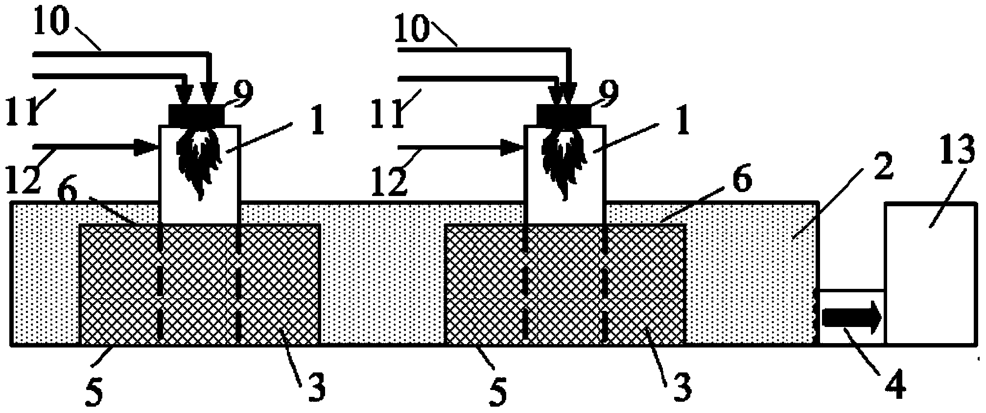
[0041] Such as figure 2 On the basis of Example 1, the two groups of high-temperature degreasing devices under pressure used at the same time are equipped with a separate set of hot flue gas generating devices 9 and share a set of exhaust gas chambers 2 . The degreasing treatment can be performed on two porous oily parts 3 at the same time, which improves production efficiency and saves operating costs.

Embodiment 3

[0043] On the basis of Example 1, more than two sets of high-temperature pressure degreasing devices are used at the same time, and each set is equipped with a separate set of hot flue gas generating devices 9 and shares a set of exhaust gas chambers 2 . More than two porous oil-bearing parts 3 can be deoiled at the same time, which can greatly improve production efficiency and save operating costs.


PUM


Abstract

The invention provides a high-temperature deoiling device under pressure. The high-temperature deoiling device under pressure comprises a waste gas chamber, a hot smoke gas inlet pipeline, a smoke gas generator and a combustion air pipeline, wherein a space for accommodating a porous oily component is formed in the waste gas chamber, the hot smoke gas inlet pipeline extends into the waste gas chamber, in addition, one end of the hot smoke gas inlet pipeline is communicated with the inside of the porous oily component, the hot smoke gas generator is arranged at the other end of the hot smoke gas inlet pipeline, the combustion air pipeline is communicated with the hot smoke gas generator, and the combustion air pipeline is provided with a pressurizing device. The hot smoke gas generated by the hot smoke gas generator forms a certain pressure under the effect of the pressurizing device, the hot smoke gas with the pressure is sent into the inside of the porous oily component through the hot smoke gas inlet pipeline, under the effect of pressure, the hot smoke gas penetrates through the porous oily component, and the combustion deoiling on grease inside the component is realized. A top sealing press sheet and a bottom sealing press sheet can prevent the short circuit phenomenon of high-pressure hot smoke gas in the work process, so good deoiling effects are obtained. The deoiling operation period of the porous oily component is shortened, and the production efficiency is improved.

Description

technical field [0001] The invention relates to the field of mechanical processing and manufacturing, and further relates to a grease removal device, in particular to a high-temperature pressure oil removal device, which can remove grease inside porous oil-carrying parts. Background technique [0002] In the manufacturing process of industrial products, in order to meet the needs of processing technology or based on the needs of protecting processing equipment, lubricating oil is usually used as the lubricating medium or cooling medium in the processing of some mechanical parts. In order to meet the product cleanliness requirements, after the parts are processed, the grease on the surface and inside of the parts needs to be thoroughly removed, otherwise the residual grease will not only easily adhere to dust and other sundries, but also affect the next processing or assembly process. The complete removal of grease inside porous mechanical parts has always been a problem that...

Claims


Application Information

Patent Timeline
Patent Type & Authority Applications(China)
IPC IPC(8): B08B7/00
Inventor 夏怀祥徐旭升李春雨王虎李小海江晓明
Owner DATANG ENVIRONMENT IND GRP
Why Eureka
Try Eureka