A hot smoke negative pressure degreasing device

A negative pressure and hot smoke technology, which is applied in the field of mechanical processing and manufacturing, can solve the problems of inapplicable removal of grease from porous mechanical parts, etc., and achieve the effects of shortening the degreasing operation cycle, good degreasing effect, and flexible operation

Active Publication Date: 2016-04-06
DATANG ENVIRONMENT IND GRP
View PDF9 Cites 0 Cited by
  • Summary
  • Abstract
  • Description
  • Claims
  • Application Information

AI Technical Summary

Problems solved by technology

This device can effectively remove the grease in parts with a single channel such as coiled tubes, but it is not suitable for removing grease inside porous mechanical parts

Method used


Image

  • A hot smoke negative pressure degreasing device

Examples


Embodiment 1

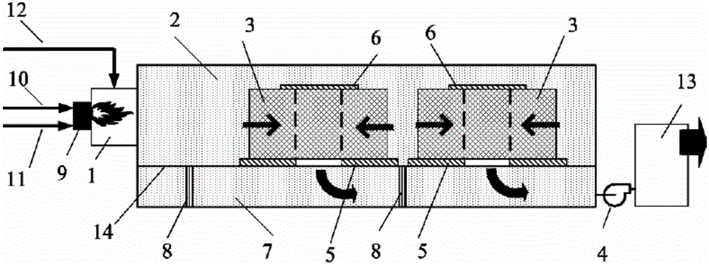
[0036] Such as figure 1The hot smoke negative pressure degreasing device shown includes a hot smoke inlet pipe 1, a high temperature gas chamber 2, a smoke exhaust fan 4, a bottom sealing pressing piece 5, a top sealing pressing piece 6, a negative pressure chamber 7, a supporting column 8, Hot smoke generating device 9, fuel pipeline 10, combustion air pipeline 11, mixed air pipeline 12, exhaust gas treatment device 13, partition 14; porous oily part 3 is placed in high temperature gas chamber 2, and hot smoke inlet pipeline 1 is connected to The high-temperature gas chamber 2 and the hot flue gas generating device 4 are located at the tail of the hot flue gas inlet pipe 1, and its tail is connected with a fuel pipe 10 and a combustion air pipe 11 to generate hot flue gas. The inside of the hot flue gas inlet pipe 1 is provided with Thermocouple and oxygen content measurement device, the measurement results can be used as the basis for adjusting the flue gas temperature and o...

Embodiment 2

[0038] On the basis of Embodiment 1, no less than 3 smoke passage holes are provided on the partition plate 14, and no less than 3 porous oily parts 3 can be treated at the same time for degreasing treatment. Improve work efficiency and save operating costs. When the number of openings on the separator 14 is more than that of the porous oil-carrying parts 3 to be processed, the top sealing sheet 6 can be used to directly seal the smoke holes to prevent short circuit of the smoke. The operational flexibility of the system is improved.

Embodiment 3

[0040] On the basis of Embodiment 1, a heat conduction device is arranged on the exhaust gas treatment device 13, and the heat generated by high-temperature combustion of exhaust gas can be used for industrial heating, domestic heating, etc., so as to achieve the purpose of fully utilizing energy. Heat can also be conducted into the high-temperature gas chamber 2 to increase the temperature in the high-temperature gas chamber 2 . It is also possible to introduce heat into the combustion air duct 11 to preheat the air. Both of these structures can speed up the processing speed, improve the processing efficiency, save costs, reduce heat loss, and better protect the environment.


PUM


Abstract

The invention provides a negative-pressure hot smoke de-oiling device. The negative-pressure hot smoke de-oiling device comprises a high-temperature gas chamber, a hot smoke gas inlet pipeline, a negative-pressure chamber and a hot smoke gas generation device, wherein the high-temperature gas chamber is provided with a space capable of containing a porous oiled part; one end of the hot smoke gas inlet pipeline is communicated with the high-temperature gas chamber; the negative-pressure chamber is separated from the high-temperature gas chamber; the hot smoke gas generation device is arranged at the other end of the hot smoke gas inlet pipeline; a position, at which the porous oiled part is placed, in the high-temperature gas chamber is communicated with the negative-pressure chamber; an air inducing device is communicated with the negative-pressure chamber so as to enable the negative-pressure chamber to be kept in a negative-pressure state. Under the action of forced flowing of high-temperature hot smoke gas of which the temperature and the oxygen content are adjustable in the porous oiled part, the porous oiled part with a complicated structure is subjected to high-temperature de-oiling treatment, so that the thorough cleaning is realized.

Description

technical field [0001] The invention relates to the field of mechanical processing and manufacturing, and further relates to a grease removal device, in particular to a hot smoke negative pressure oil removal device, which can remove grease inside porous oily parts. Background technique [0002] In the manufacturing process of industrial products, in order to meet the needs of processing technology or based on the needs of protecting processing equipment, lubricating oil is usually used as the lubricating medium or cooling medium in the processing of some mechanical parts. In order to meet the product cleanliness requirements, after the parts are processed, the grease on the surface and inside of the parts needs to be thoroughly removed, otherwise the residual grease will not only easily adhere to dust and other sundries, but also affect the next processing or assembly process. The complete removal of grease inside porous mechanical parts has always been a problem that plagu...

Claims


Application Information

Patent Timeline
Patent Type & Authority Patents(China)
IPC IPC(8): B08B7/00
Inventor 李春雨王虎李小海徐旭升江晓明夏怀祥
Owner DATANG ENVIRONMENT IND GRP
Why Eureka
Try Eureka