Method for controlling steel throwing distance of hot-rolling reversing roughing mill

A control method and rough rolling mill technology, applied in the direction of rolling mill control devices, metal rolling, metal rolling, etc., can solve the problems that slabs cannot be rolled normally, the program cannot be reached, and affect the smooth rolling of the rolling mill, so as to avoid The effect of slab failure to normal rolling accidents, improving the rolling rhythm, and avoiding serious fault alarms

Inactive Publication Date: 2013-12-18
SHOUGANG JINGTANG IRON & STEEL CO LTD
View PDF3 Cites 4 Cited by
  • Summary
  • Abstract
  • Description
  • Claims
  • Application Information

AI Technical Summary

Problems solved by technology

[0004] At present, the steel throwing distance of the rough rolling mill is often too far when the speed of the flat roll mill is increased, resulting in a long pass interval of the rolling mill, which seriously affects the rolling rhythm of the rough rolling area; or because the speed of the flat roll mill is reduced. As a result, the slab is not thrown out of the rough rolling mill, and the thermal inspection before and after the rough rolling mill causes the program to fail to reach the next step, and the slab cannot be rolled normally, which seriously affects the smooth rolling of the rolling mill, and the control method of the steel throwing distance must be changed

Method used


Image

  • Method for controlling steel throwing distance of hot-rolling reversing roughing mill
  • Method for controlling steel throwing distance of hot-rolling reversing roughing mill
  • Method for controlling steel throwing distance of hot-rolling reversing roughing mill

Examples


Embodiment Construction

[0016] In order to make the object, technical solution and advantages of the present invention clearer, the present invention will be further described in detail below in conjunction with the accompanying drawings.

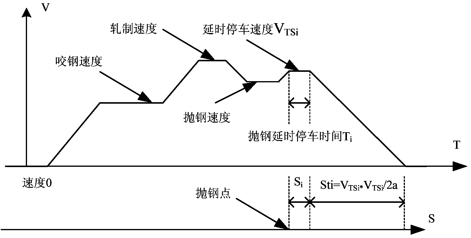
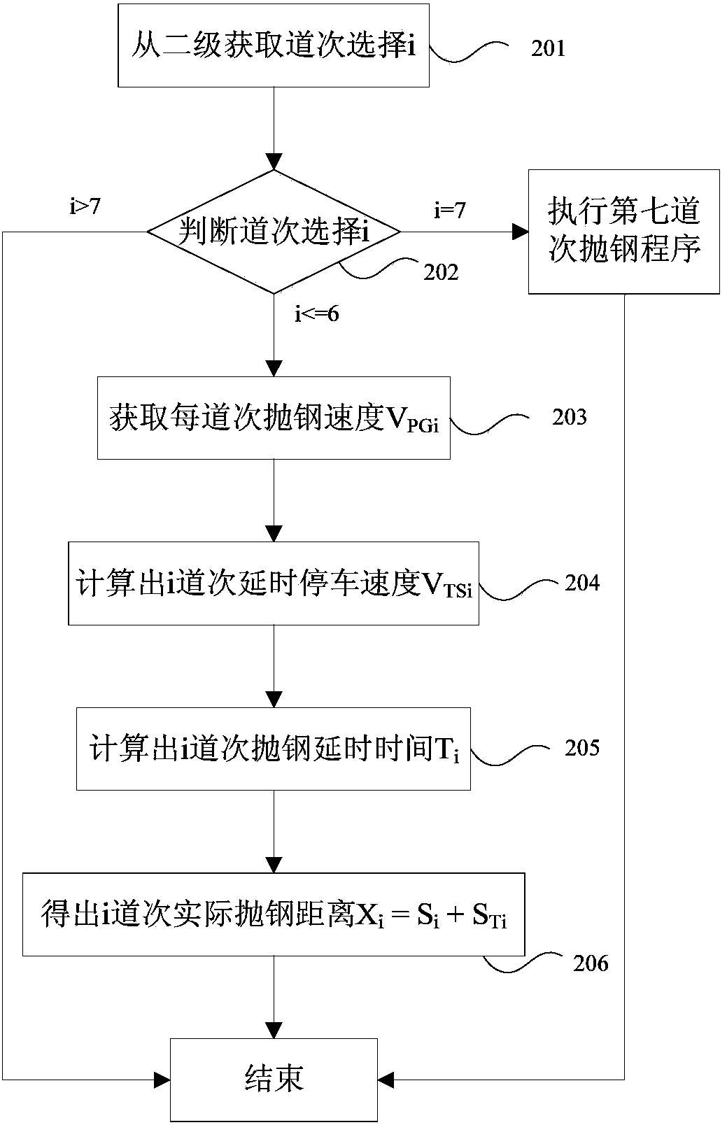
[0017] In the method for controlling the throwing distance of the hot rolling reversible roughing mill provided by the embodiment of the present invention, the delayed stop speed V of each pass is obtained first by calculation. Tsi (Such as figure 1 shown corresponding to the position of the actual steel throwing point of the rolling mill), and then set the steel throwing delay distance constants from the first pass to the sixth pass, which are respectively S 1 , S 2 , S 3 , S 4 , S 5 , S 6 , according to the formula T i =S i / V TSi , calculate the steel throwing delay time from the first pass to the sixth pass as T 1 , T 2 , T 3 , T 4 , T 5 , T 6 , and finally calculate the actual steel throwing distance X from the first pass to the sixth pass 1 、X...


PUM


Abstract

The invention discloses a method for controlling a steel throwing distance of a hot-rolling reversing roughing mill and belongs to the field of the metallurgical industry. The method comprises the following steps: a, acquiring a pass selection i from a second stage, executing the step b if i is less than or equal to 6, executing a seventh pass steel throwing program and then finishing the process if i is equal to 7, or finishing the process; b, setting a steel throwing speed in each pass into VPGi and assigning the steel throwing speed corresponding to the pass i in the variable VPGi; c, by a formula VTSi=VPGi+VC, acquiring a time-delay shutdown speed VTSi in the pass i; d, by a formula Ti=Si/VTSi, acquiring a steel throwing delay time Ti in the pass i; and e, acquiring the actual steel throwing distance Xi=Si+STi in the pass i. According to the method, the actual steel throwing distance of a slab is guaranteed to be accurately controlled in the effective range of hot detection in the front of a rolling mill and reversed water spraying behind the rolling mill; the rolling cycle of a roughing region is improved; and serious fault alarm of transmission and an accident that the slab cannot be normally rolled are avoided.

Description

technical field [0001] The invention relates to the field of metallurgical industry, in particular to a method for controlling the throwing distance of a reversible rough rolling mill for hot rolling. Background technique [0002] The rough rolling mill is an important equipment of the hot rolling production line. Through the odd and even pass control of the rough rolling mill (the rolling direction of the odd pass is the direction of the finishing mill; the rolling direction of the even pass is the direction of the heating furnace), the slab is rolled into the middle slab thickness, and then sent to the finishing mill to be rolled into finished strip steel. [0003] The flat roll mill in the rough rolling area of ​​hot rolling generally includes a two-high rough rolling mill (named R1) and a four-high rough rolling mill (named R2); the R1 rolling mill is upstream, and the R2 rolling mill is downstream; there are connecting roller tables and entrance roller tables before R1 ...

Claims


Application Information

Patent Timeline
Patent Type & Authority Applications(China)
IPC IPC(8): B21B37/00
Inventor 毕立军赵继武汪万根王文忠刘京涛孙会杰
Owner SHOUGANG JINGTANG IRON & STEEL CO LTD
Why Eureka
Try Eureka