Eureka AIR delivers breakthrough ideas for toughest innovation challenges, trusted by R&D personnel around the world.

Automatic butt-joint welder for panels of lock sets

A butt welding machine and panel technology, applied in welding equipment, manufacturing tools, resistance welding equipment, etc., can solve the problems of inconvenient operation, low work efficiency, unstable welding quality, etc., and achieve convenient operation, stable welding quality, and work high efficiency effect

Inactive Publication Date: 2013-12-18
东莞市好的照明科技有限公司
View PDF0 Cites 7 Cited by
  • Summary
  • Abstract
  • Description
  • Claims
  • Application Information

AI Technical Summary

Problems solved by technology

[0003] When manufacturing locks, we usually weld studs and pins on the lock panel, but the welding technology currently used in this industry mostly uses butt welding technology, but the butt welding machines in the prior art are mostly manual operations, and workers are left and right handed. Take a workpiece each, put it on the welding head of the butt welding machine, and then use the foot switch to weld, or the worker holds the welding machine with a cylinder in his hand, and directly applies pressure to the working product to achieve the purpose of butt welding, which is inconvenient to operate , the work efficiency is low, the welding quality is unstable, and the traditional butt welding machine is generally driven between the cylinders to generate lifting motion, which drives the welding needle to weld, so that the welding workpiece will be directly stressed, and usually there is a gap between the welding workpiece and the welding head At a certain distance, the action of the cylinder produces an instantaneous impact force, which will affect the welding effect, so we need to find a more advanced butt welding machine, which makes the operation more convenient, the work efficiency is higher, and the welding quality is more stable

Method used


Image

  • Automatic butt-joint welder for panels of lock sets
  • Automatic butt-joint welder for panels of lock sets
  • Automatic butt-joint welder for panels of lock sets

Examples


Embodiment Construction

[0023] In order to better understand the technical content of the present invention, a specific embodiment is provided below, and the present invention is further described in conjunction with the accompanying drawings.

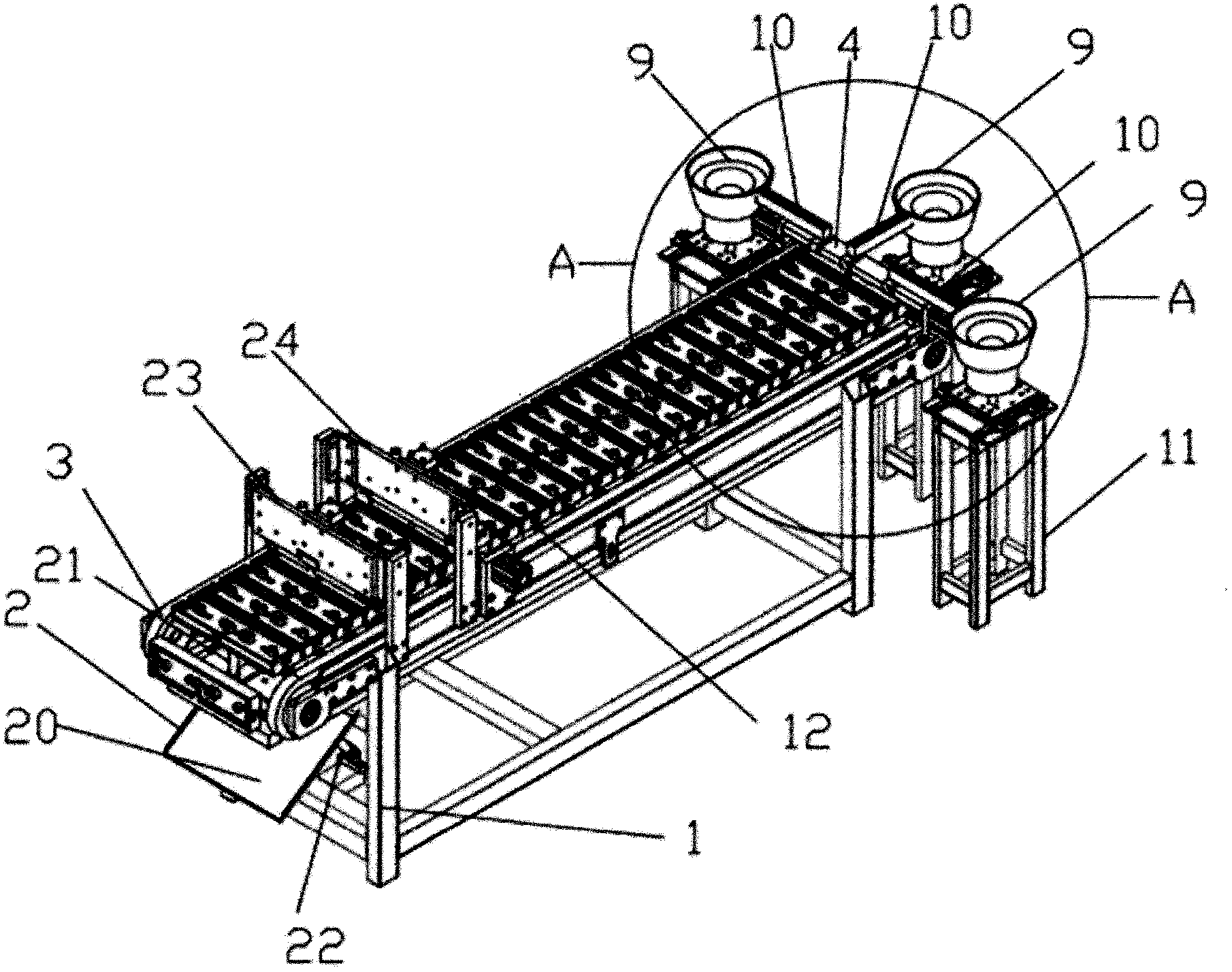
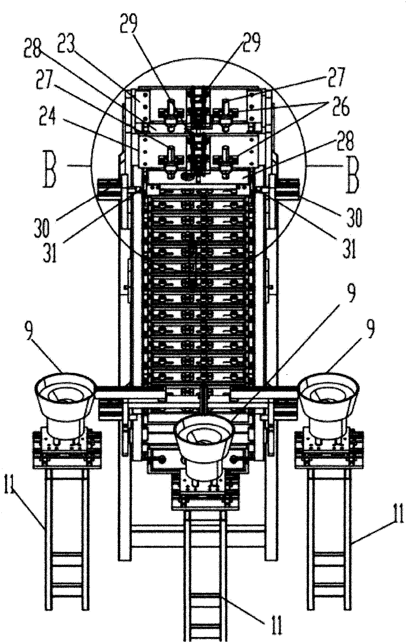
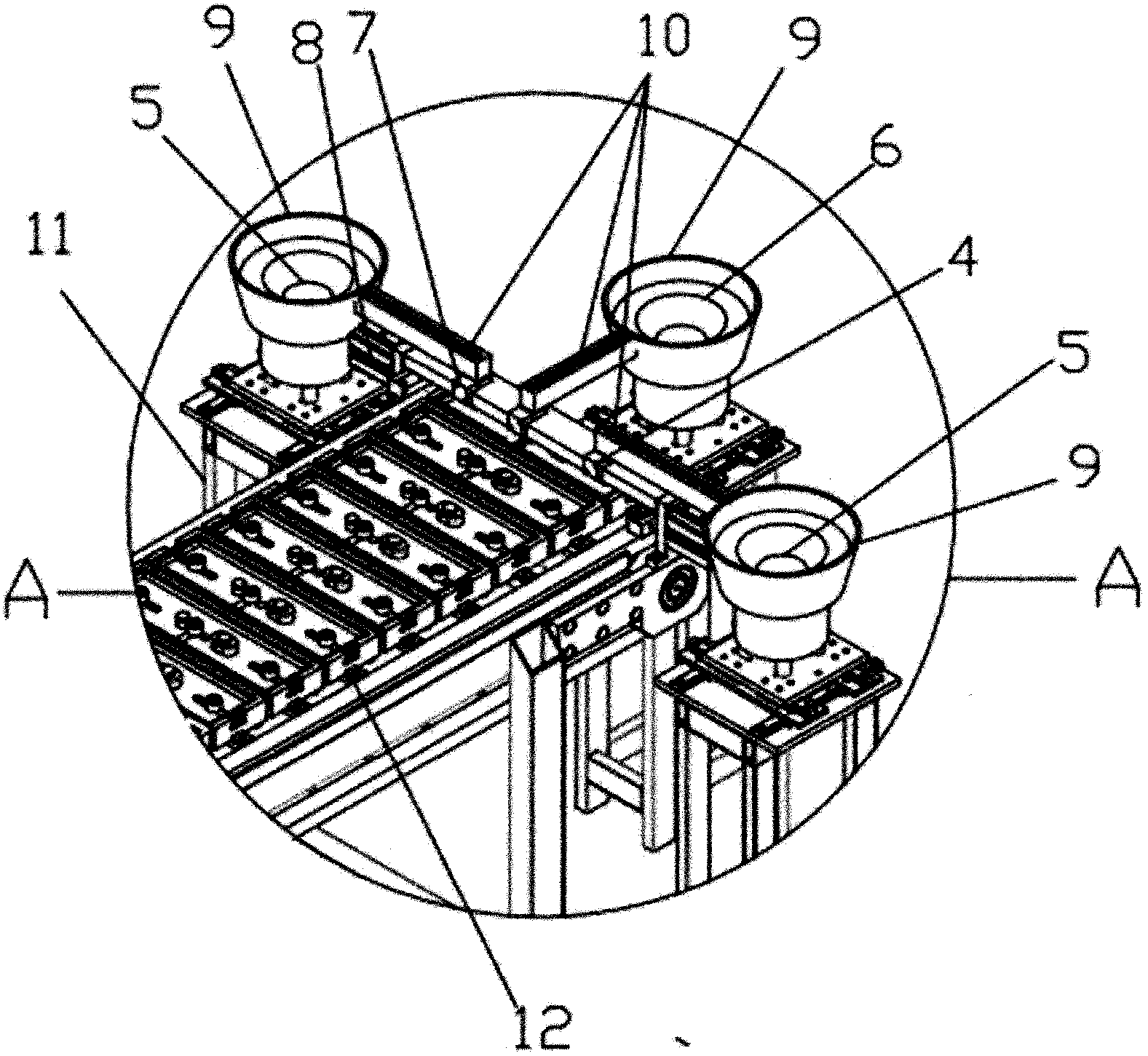
[0024] In this embodiment, refer to Figure 1 to Figure 7 , a kind of automatic butt welding machine of lock panel, it comprises frame 1, and the feeding mechanism that is arranged on frame 1 one end (such as image 3 ), and the blanking mechanism 2 that is arranged on the other end of the frame, and the transmission mechanism 3 that is arranged on the frame 1, and some working modules that are arranged on the transmission mechanism 3 (such as Figure 5 ), and the butt welding mechanism fixed on the frame 1 (such as Figure 4 ), in addition, a PLC control system is provided to control the entire mechanical operation steps.

[0025] The feeding mechanism (such as image 3 ) includes the blanking module 4, the stud feeding mechanism 5 and the pin feeding mec...


PUM


Abstract

The invention discloses an automatic butt-joint welder for panels of lock sets. The automatic butt-joint welder comprises a frame, a feeding mechanism, a discharging mechanism, a driving mechanism, a plurality of working modules, a butt-joint welding mechanism and a PLC (programmable logical controller) control system. The feeding mechanism is arranged at one end of the frame, the discharging mechanism is arranged at the other end of the frame, the driving mechanism is arranged on the frame, the working modules are arranged on the driving mechanism, the butt-joint welding mechanism is fixed on the frame, and the PLC control system controls the whole machining procedure. The automatic butt-joint welder is mainly applied to butt-joint welding of the panels of the lock sets and bolts or butt-joint welding of the panels and pins. The operation steps of the conventional butt-joint welder are integrated to the same machine, the feeding, the butt-joint welding and the product recovery are integrated, the advanced PLC control system is introduced, and therefore, automatic operation is achieved, operational convenience and working efficiency are higher, and welding quality is more stable.

Description

technical field [0001] The invention relates to the field of welding technology, in particular to an automatic butt welding machine for welding lock panels. Background technique [0002] As a branch of welding technology, butt welding technology is used in various fields due to its excellence. The principle of butt welding is: the work piece is opposite to the chuck, and the two ends of the joint are pressed against each other, and a large amount of current is guided to the work piece through the chuck. First, high temperature is generated through the contact surface, and when the metal reaches a plastic state, an appropriate pressure is applied on the moving end to squeeze the two ends together. According to the principle of butt welding, we invented the butt welding machine. The welding principle is to use welding The resistance heat of the region itself and a large amount of plastic deformation energy make the two separated metal atoms close to the lattice distance to for...

Claims


Application Information

Patent Timeline
Patent Type & Authority Applications(China)
IPC IPC(8): B23K11/00B23K11/36
Inventor 陶横亮
Owner 东莞市好的照明科技有限公司
Why Eureka
Eureka Blog
Learn More