Eureka AIR delivers breakthrough ideas for toughest innovation challenges, trusted by R&D personnel around the world.

Intelligent 3D printing powder supply device

A powder supply device and 3D printing technology, applied to 3D object support structures, metal processing equipment, manufacturing tools, etc., can solve the problem of insufficient automation of 3D printing powder supply devices, and achieve reduced manual operations, scientific and reasonable structure, and convenient use Efficient effect

Inactive Publication Date: 2017-02-15
CHENGDU KECHUANGCHENG TECH
View PDF0 Cites 0 Cited by
  • Summary
  • Abstract
  • Description
  • Claims
  • Application Information

AI Technical Summary

Problems solved by technology

[0002] 3D printing technology appeared in the mid-1990s. It is actually the latest rapid prototyping device using technologies such as light curing and paper lamination. It works basically the same as ordinary printing. The printer is filled with "printing materials" such as liquid or powder. After the computer is connected, the "printing material" is superimposed layer by layer through computer control, and finally the blueprint on the computer is turned into a real object. In 1986, American scientist Charles Hull developed the first commercial 3D printing machine. In 1993, Massachusetts The Institute of Technology obtained the patent for 3D printing technology. In 1995, ZCorp of the United States obtained the sole authorization from the Massachusetts Institute of Technology and began to develop 3D printers. In 2005, the first high-definition color 3D printer Spectrum Z510 on the market was successfully developed by ZCorp in 2010. In November, the Jim Kor team in the United States created the world's first car Urbee printed by a 3D printer, but the traditional 3D printing powder supply device is not automatic enough and requires a certain amount of manual operation

Method used


Image

  • Intelligent 3D printing powder supply device
  • Intelligent 3D printing powder supply device
  • Intelligent 3D printing powder supply device

Examples


Embodiment Construction

[0014] The following will clearly and completely describe the technical solutions in the embodiments of the present invention with reference to the accompanying drawings in the embodiments of the present invention. Obviously, the described embodiments are only some, not all, embodiments of the present invention. Based on the embodiments of the present invention, all other embodiments obtained by persons of ordinary skill in the art without making creative efforts belong to the protection scope of the present invention.

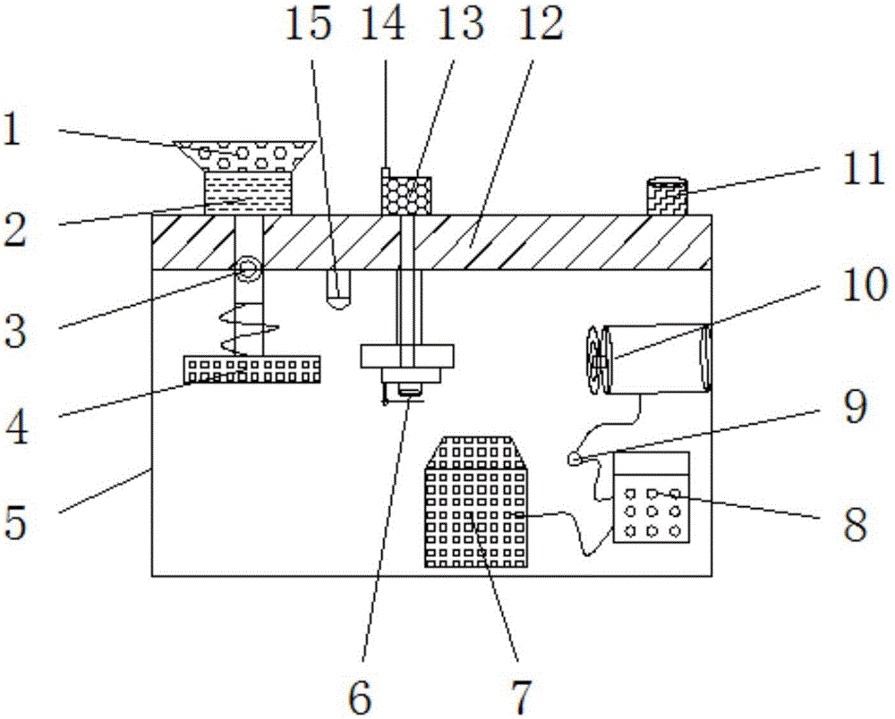
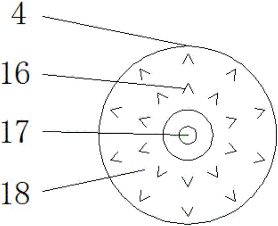
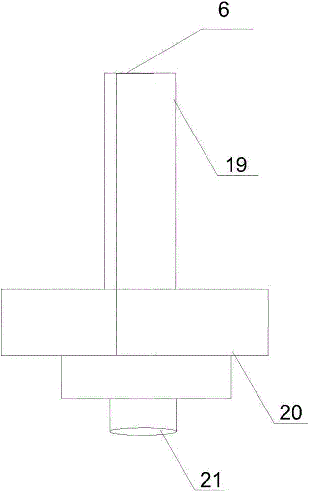
[0015] see Figure 1-3 , an embodiment provided by the present invention: an intelligent 3D printing powder supply device, including a working body 4, a control device 8, a power device 10 and an induction device 15, a rotation center 17 is installed in the center of the working body 4, and the rotation center 17 is equipped with a rotating casing 18 on the outside, and a powder supply opening 16 is arranged on the rotating casing 18. An organic casing 5 is in...


PUM


Abstract

The invention discloses an intelligent 3D printing powder supply device which comprises a working body, a control device, a power device and an induction device. A rotary center is installed in the center of the interior of the working body. A rotary shell is installed on the outer portion of the rotary center and provided with a powder supply opening. A machine housing is installed on the outer side of the working body. A powder supply adhesive device is installed on the upper portion of the interior of the machine housing. A nozzle is formed in the bottom end of the interior of the powder supply adhesive device, and a pressing device is installed above the nozzle. A connecting rod is installed on the upper portion of the pressing device. A data processing device is installed below the powder supply adhesive device. The control device is installed on one side of the data processing device. A PLC electric control unit is installed at one end of the control device, and the control device is connected with the power device through the PLC electric control unit. A working indicating lamp is installed on the upper right portion of the power device. The intelligent 3D printing powder supply device is wide in application range and convenient to use.

Description

technical field [0001] The invention relates to the technical field of 3D printing powder supply equipment, in particular to an intelligent 3D printing powder supply device. Background technique [0002] 3D printing technology appeared in the mid-1990s. It is actually the latest rapid prototyping device using technologies such as light curing and paper lamination. It works basically the same as ordinary printing. The printer is filled with "printing materials" such as liquid or powder. After the computer is connected, the "printing material" is superimposed layer by layer through computer control, and finally the blueprint on the computer is turned into a real object. In 1986, American scientist Charles Hull developed the first commercial 3D printing machine. In 1993, Massachusetts The Institute of Technology obtained the patent for 3D printing technology. In 1995, ZCorp of the United States obtained the sole authorization from the Massachusetts Institute of Technology and b...

Claims


Application Information

Patent Timeline
IPC IPC(8): B29C64/141B29C64/321B33Y30/00
CPCB33Y30/00B33Y40/00
Inventor 王明洋蒋星华
Owner CHENGDU KECHUANGCHENG TECH
Why Eureka
Eureka Blog
Learn More