Quantitative pushing device for air valve spring gaskets on engine cylinder cover

An engine cylinder head and valve spring technology, which is applied in metal processing, metal processing equipment, manufacturing tools, etc., can solve the problems of inability to accurately remove gaskets, missing installation, and difficult to find, so as to improve assembly quality and assembly speed. Effect

Inactive Publication Date: 2013-12-18
CHERY AUTOMOBILE CO LTD
View PDF15 Cites 8 Cited by
  • Summary
  • Abstract
  • Description
  • Claims
  • Application Information

AI Technical Summary

Problems solved by technology

The method currently adopted is that the operator takes out 12-14 gaskets from the stacked material boxes and assembles them to the specified positions in sequence. At present, the main problems are: 1. Due to the thinner gaskets and the large number of one-time assembly, the operation It is easy for the operator to miss or overfill in the long-term work, and it is not easy to find out, which will eventually lead to the rework of the whole machine and the scrapping of parts; 2. The operator cannot accurately take out the right amount of pads from the material box If you take a small amount, you need to take it twice, and when you take a lot, you need to send it back, resulting in a waste of action

Method used


Image

  • Quantitative pushing device for air valve spring gaskets on engine cylinder cover
  • Quantitative pushing device for air valve spring gaskets on engine cylinder cover

Examples


Embodiment 1

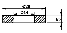
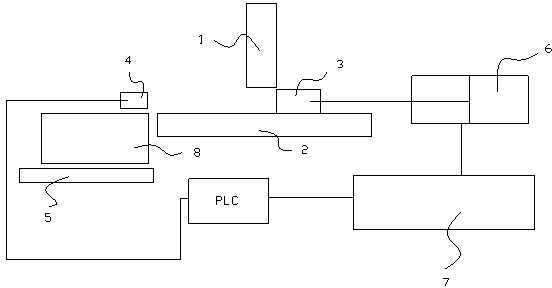
[0015] Such as figure 2 , the engine cylinder head valve spring gasket quantitative pushing device of the present invention comprises a vertically placed barrel 1, the diameter of the barrel 1 matches the diameter of the spring washer, the bottom of the barrel 1 is a base plate 2, and the lower end of the barrel 1 is in contact with the spring washer. Between the substrates 2 is a pusher block 3, the height of the pusher block 3 is greater than N-1 times the thickness of the spring washer and less than N times the thickness of the spring washer, N is the quantity of the spring washer pushed each time, and the barrel The distance between the lower end of 1 and the substrate 2 is greater than N times the thickness of the spring washer and less than N+1 times the thickness of the spring washer, and the pushing block 3 can reciprocate horizontally between the barrel 1 and the substrate 2 .

[0016] The present invention also includes proximity switch 4, and proximity switch 4 is ...


PUM


Abstract

The invention provides a quantitative pushing device for air valve spring gaskets on an engine cylinder cover, which can be used for quantitatively pushing spring gaskets needed during assembling of an engine cylinder cover assembly. The device comprises a charging barrel which is arranged vertically, wherein the diameter of the charging barrel is matched with the diameters of the spring gaskets; a substrate is arranged below the charging barrel; a material pushing block is arranged between the lower end of the charging barrel and the substrate; the height of the pushing block is larger than a thickness which is (N-1) times larger than the thickness of each spring gasket and is smaller than a thickness which is N times larger than the thickness of each spring gasket; N refers to the fixed quantity of the spring gaskets pushed each time; the distance between the lower end of the charging barrel and the substrate is larger than a thickness which is N times larger than the thickness of each spring gasket and is smaller than a thickness which is (N+1) times larger than the thickness of each spring gasket; the material pushing block can move between the charging barrel and the substrate along a horizontal direction in an reciprocating way. During working, the spring gaskets fall onto the substrate freely in the charging barrel; when an operator needs spring gaskets, the material pushing block is used for pushing spring gaskets of a certain height out of the charging barrel along the substrate and away from the charging barrel, the material pushing block returns after the needed spring gaskets are put in place, and the spring gaskets in the charging barrel fall freely to fill the blanks.

Description

technical field [0001] The invention relates to the technical field of assembly tooling for automobile parts, in particular to a quantitative pushing device for an engine cylinder head valve spring gasket. Background technique [0002] When assembling the cylinder head assembly in the engine manufacturing process, it is necessary to install the valve spring gasket on the valve base and then assemble the valve oil seal, valve, spring, and lock piece. The valve spring gasket is a thickness of 0.5mm and a diameter of 28mm, a circular gasket with a central hole diameter of 14mm, such as figure 1 shown. A finished cylinder head needs to be equipped with 12-14 gaskets. The method currently adopted is that the operator takes out 12-14 gaskets from the stacked material boxes and assembles them to the specified positions in sequence. At present, the main problems are: 1. Due to the thinner gaskets and the large number of one-time assembly, the operation It is easy for the operato...

Claims


Application Information

Patent Timeline
Patent Type & Authority Applications(China)
IPC IPC(8): B23P19/00
Inventor 程龙詹江栋苗为王海洋夏有平
Owner CHERY AUTOMOBILE CO LTD
Why Eureka
Try Eureka