
Clamp for measuring milling force for milling and processing blade fixed inclining angle

A technology of milling processing and milling force, which is applied in the direction of manufacturing tools, metal processing equipment, measuring/indicating equipment, etc., can solve problems such as difficult measurement of milling force, and achieve the effects of high positioning accuracy, convenient installation, and simple fixture structure

Active Publication Date: 2013-12-18
西安三航动力科技有限公司
View PDF8 Cites 7 Cited by
  • Summary
  • Abstract
  • Description
  • Claims
  • Application Information

AI Technical Summary

Problems solved by technology

[0005] In order to avoid the deficiencies in the existing technology, aiming at the problem that the milling force is difficult to measure during the milling process of the blade with a fixed inclination angle

Method used


Image

  • Clamp for measuring milling force for milling and processing blade fixed inclining angle
  • Clamp for measuring milling force for milling and processing blade fixed inclining angle

Examples


Embodiment Construction

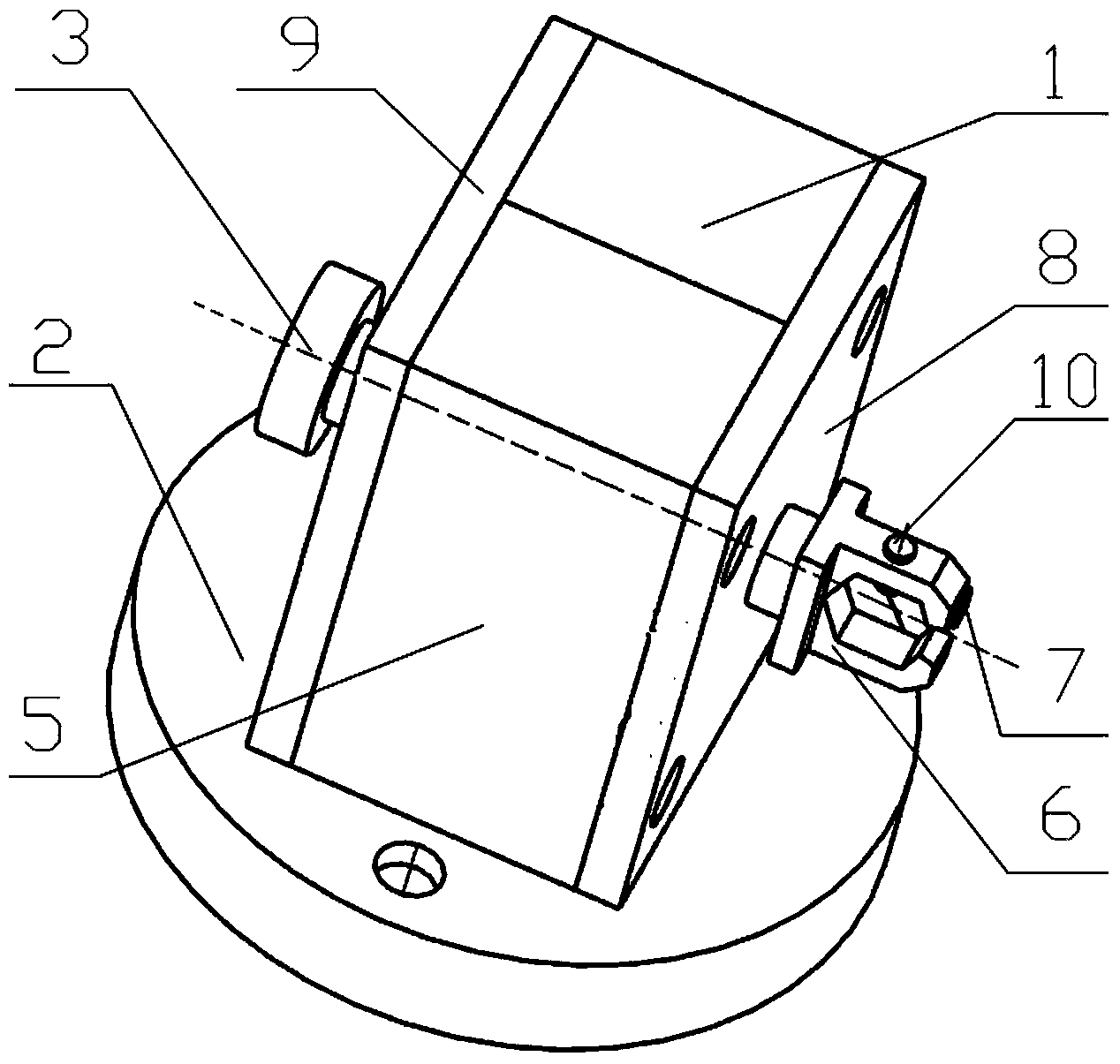
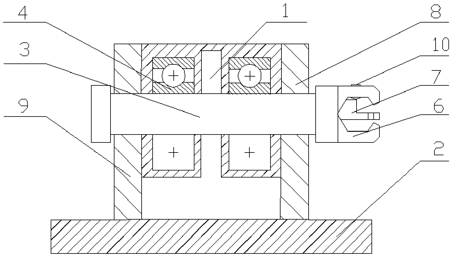
[0015] This embodiment is a fixture used for measuring milling force in milling of a blade with a fixed inclination angle. The fixture for measuring the milling force of blade fixed-inclination milling is installed on the force measuring platform of the dynamometer through bolts, and the dynamometer is installed on the machine tool table.

[0016] refer to figure 1 , figure 2 , the jig for measuring the milling force of blade fixed inclination angle milling in the present invention consists of a clamp body, a base 2, a rotating shaft 3, a bearing 4, a clamping positioning block 6, an auxiliary positioning block 7, a first baffle plate 8, a second baffle plate 9, Fastening pin 10 forms. The base 2 is a circular structure fixed on the force measuring platform of the force measuring instrument. The clamp body includes a first clamp body 1 and a second clamp body 5. The first clamp body 1 and the base 2 are of an integral structure. There are two bearing slots with the same sh...


PUM


Abstract

The invention discloses a clamp for measuring milling force for milling and processing blade fixed inclining angle, and belongs to the technical field of processing of aero-engine blades. The clamp for measuring the milling force for milling and processing the blade fixed inclining angle is arranged on a force measuring table of a dynamometer through bolts, and the dynamometer is arranged on a worktable of a machine tool. When the milling force in the blade processing process is measured, a blade tenon root is fixedly arranged on a clamping and positioning block at the end part of a rotary shaft of the clamp. The rotation form of a chuck is transferred to the rotary shaft of the clamp through a transmission shaft, a blade clamped at one end of the rotary shaft rotates together with the rotary shaft, and the inclining angle between a cutter shaft and the blade is kept consistent. The clamp for measuring the milling force for milling and processing the blade fixed inclining angle is arranged on the force measuring table of the dynamometer through the bolts, the fixed inclining angle is processed by the measuring clamp, and the milling force is measured on the force measuring table of the dynamometer. The clamp has the advantages that the structure is simple, the installation is convenient, the positioning precision is high, and the effect on the positioning precision due to multiple times of detachment is avoided.

Description

technical field [0001] The invention belongs to the technical field of aero-engine blade processing, and in particular relates to a fixture for measuring milling force during blade fixed-inclination milling. Background technique [0002] In the existing aero-engine manufacturing and processing technology, the processing of compressor and fan blades is more difficult, especially aero-engines require a high thrust-to-weight ratio, and the design of the blades requires high precision and light weight, and thin-walled structures and titanium alloys are often used These characteristics make the inclination angle between the tool and the blade constantly change during the machining process of the blade, which in turn makes the actual milling depth and milling speed of the tool constantly change during the milling process, making the blade In the process of milling, it is greatly affected by the milling force, and the milling force is an important cause of flutter of thin-walled bl...

Claims


Application Information

Patent Timeline
Patent Type & Authority Applications(China)
IPC IPC(8): B23Q3/06B23Q17/09
Inventor 刘维伟万旭生李晓燕
Owner 西安三航动力科技有限公司
Learn More