
Auxiliary device for installing connecting pipe of oil cooling pipe of cooler

A technology for installation assistance and oil-cooled tubes, which is applied to hand-held tools and manufacturing tools, can solve the problems of waste of human resources and low efficiency, and achieve the effects of accelerating production efficiency, avoiding repeated correction of angles, and saving resources

Inactive Publication Date: 2013-12-18
SUZHOU CHENHAO TEXTILE TECH CO LTD
View PDF8 Cites 2 Cited by
  • Summary
  • Abstract
  • Description
  • Claims
  • Application Information

AI Technical Summary

Problems solved by technology

The oil cooling tube is a kind of heat exchanger, which mainly cools the oil in the oil cooling tube through water. Since the oil cooling tube and the pipeline in the car are installed in various positions, it is required to connect the oil cooling tube to the oil pipe of the car. The angle of the connecting pipe is also varied, but now two people are required to install the connecting pipe of the oil cooling pipe at the same time. One person needs to control the angle of the connecting pipe, and the other person holds down the radiator and tightens it with a wrench. Formal installation is not only a waste of human resources, but also less efficient

Method used


Image

  • Auxiliary device for installing connecting pipe of oil cooling pipe of cooler
  • Auxiliary device for installing connecting pipe of oil cooling pipe of cooler
  • Auxiliary device for installing connecting pipe of oil cooling pipe of cooler

Examples


Embodiment Construction

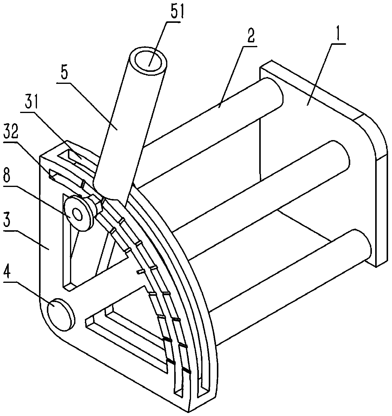
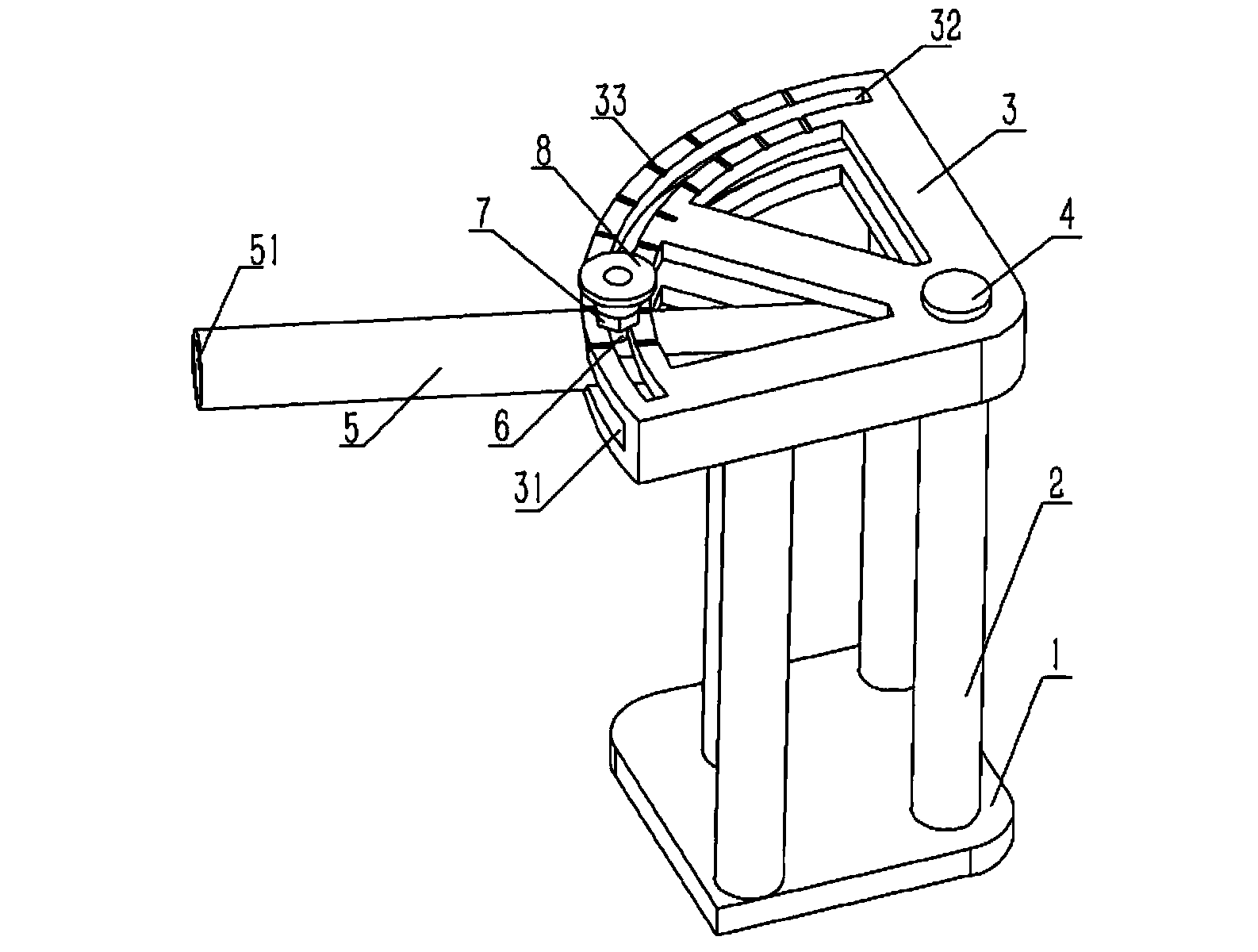
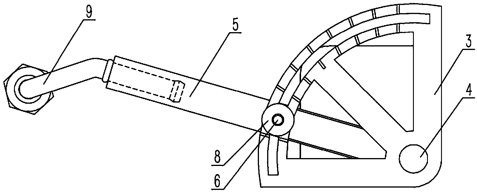
[0014] Example: see figure 1 , 2 As shown, a radiator oil cooling pipe connection installation auxiliary device includes a base 1, the base 1 is fixed on the workbench, the support column 2 is fixed on the base 1, the upper end of the support column 2 is fixed with a fan-shaped bracket 3, and the fan-shaped bracket 3 The inside is formed with a fan-shaped groove cavity 31 that runs through the arc side of the fan-shaped bracket 3, and a fan-shaped annular groove 32 that runs through the upper and lower end faces is formed on the fan-shaped bracket 3 near the arc side of the fan-shaped bracket 3, and one end of the auxiliary rod 5 passes through the fan-shaped bracket. 3, the fan-shaped cavity 31 is hinged on the fan-shaped bracket 3 through the pin shaft 4, and the other end surface of the auxiliary rod 5 is formed with a slot 51. The auxiliary rod 5 is provided with bolts 6, and the bolts 6 pass through the fan-shaped bracket in turn. The fan ring groove 32 on the lower plan...


PUM


Abstract

The invention relates to an auxiliary device for installing a connecting pipe of an oil cooling pipe of a cooler. The auxiliary device comprises a base which is fixed on a working platform; a support pillar is fixed on the base; a fan-shaped bracket is fixed at the upper end of the support pillar; a fan-shaped groove cavity which passes through the fan-shaped bracket and has an circular arc-shaped side is molded in the fan-shaped bracket; a fan ring-shaped groove which passes through the upper end surface and the lower end surface is molded on the fan-shaped bracket at the position close to the circular arc-shaped side of the fan-shaped groove cavity; one end of an auxiliary rod passes through the fan-shaped groove cavity of the fan-shaped bracket and is articulated on the fan-shaped bracket by a pin shaft; a slotted hole is molded on the other end surface of the auxiliary rod by lathing; the auxiliary rod is provided with a bolt; the bolt sequentially passes through the fan ring-shaped groove and the auxiliary rod which are arranged on the plane of the lower end of the fan-shaped bracket, and the fan ring-shaped groove on the plane of the upper end of the fan-shaped bracket, and is connected with a nut by screw threads; a handle is welded on the nut. After the auxiliary device is adopted, the connecting pipe can be installed only by one person, so that the resource can be saved; furthermore, the auxiliary device is fixed at the same position so as to adapt to the installation of connecting pipes with the same angle, so that the process that a worker repeatedly corrects the angle can be avoided, and the production efficiency is improved.

Description

Technical field: [0001] The invention relates to the technical field of radiator auxiliary devices, in particular to an auxiliary device for arranging radiator oil cooling pipe joints. Background technique: [0002] The current automobiles are divided into two categories: manual transmission and automatic transmission, and the radiator as the cooling core of the automobile engine is also different according to the manual transmission and automatic transmission of the car. Generally, the radiator on the existing manual transmission is not installed. Oil-cooled tubes, and the radiators of automatic transmissions are generally equipped with oil-cooled tubes in order to increase their heat dissipation efficiency. The oil cooling tube is a kind of heat exchanger, which mainly cools the oil in the oil cooling tube through water. Since the oil cooling tube and the pipeline in the car are installed in various positions, it is required to connect the oil cooling tube to the oil pipe ...

Claims


Application Information

Patent Timeline
Patent Type & Authority Applications(China)
IPC IPC(8): B25B27/14
Inventor 朱雷
Owner SUZHOU CHENHAO TEXTILE TECH CO LTD
Learn More