X-ray imaging method with automatic correction function

An automatic correction and imaging method technology, applied in the field of X-ray imaging, can solve the problems of inconvenient use

Active Publication Date: 2015-04-29
ZHEJIANG KANGYUAN MEDICAL DEVICE
View PDF4 Cites 0 Cited by
  • Summary
  • Abstract
  • Description
  • Claims
  • Application Information

AI Technical Summary

Problems solved by technology

If the conditions of the imaging system change, the system may need to be re-corrected, which is inconvenient for our actual use

Method used


Image

  • X-ray imaging method with automatic correction function
  • X-ray imaging method with automatic correction function
  • X-ray imaging method with automatic correction function

Examples


Embodiment Construction

[0014] Combine below Figure 1 to Figure 4 Specific instructions for X-ray imaging methods with automatic correction:

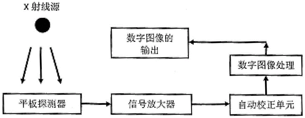
[0015] Such as figure 1 As shown, firstly, the X-ray source directly irradiates the point light source to the flat panel detector, and the flat panel detector receives the image signal; secondly, the image signal is amplified by the signal amplifier and enters the automatic correction unit for correction; finally, the corrected image is The digital image processing unit outputs after processing.

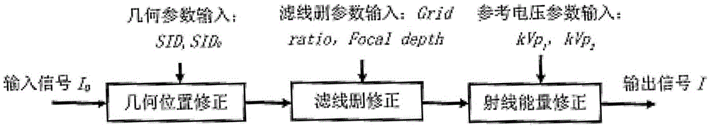
[0016] Such as figure 2 As shown, the automatic correction unit can be composed of several parts: geometric corrections, component-induced corrections (such as filter line deletion), and X-ray energy corrections. Through the automatic correction unit, the output signal I(x,y) and the input signal I 0 The relation of (x, y) is I(x, y)=G 0 (x,y)×S(x,y)×I 0 (x, y), where (x, y) is the image space coordinates, G 0 (x, y) is the distance SID from a specific ray s...


PUM


Abstract

The invention discloses an X-ray imaging method with an automatic correction function. The method includes that first, the point light source of an X-ray source directly irradiates to a flat panel detector, and the flat panel detector receives image signals; second, the image signals are amplified through a signal amplifier and then enter into an automatic correction unit for correction, the relation between an output signal I (x, y) and an output signal I0 (x, y) of the automatic correction unit is that I (x, y) =G0(x, y)* S (x, y)* I0 (x, y), wherein the (x, y) is an image space coordinate, G0(x, y) is a sensitivity correction function of a detector, and S (x, y) is a system automatic correction function; and at last, corrected images are processed by a digital image processing unit and then output. According to the imaging system, under a changing condition, without the need for repeated correction, an optimal image can still be developed.

Description

technical field [0001] The present invention relates to X-ray imaging methods. Background technique [0002] Usually our digital X-ray imaging system uses an X-ray flat panel detector (Flat Panel) to accept directly projected X-rays for imaging. If quantum noise is not considered, the ideal state is that when an X-ray point source directly irradiates the flat-panel detector, the signal intensity received by the ideal flat-panel detector looks like an image with uniform spatial distribution (usually a simple center can be used value or low-pass filtering methods to reduce quantum noise). Since the sensitivity of each pixel unit on the actual flat panel detector to receive signals is different, the brightness of the image is not uniform. For this reason, the sensitivity of each pixel unit needs to be corrected. A common method is to correct the relationship between the known different incident radiation intensity signals and the output electrical signal by using a linear fi...

Claims


Application Information

Patent Timeline
Patent Type & Authority Patents(China)
IPC IPC(8): G03B42/02
Inventor 陈建锋
Owner ZHEJIANG KANGYUAN MEDICAL DEVICE
Why Eureka
Try Eureka