
Extreme low-altitude drop device

A technology of ultra-low and shock-absorbing devices, which can be used in launching devices, transportation and packaging, and aircraft parts. It can solve problems such as waste, damaged goods, and untimely opening of parachutes, and achieve the effects of recycling and avoiding the impact of turbulent airflow.

Inactive Publication Date: 2013-12-18
JINLING INST OF TECH
View PDF5 Cites 17 Cited by
  • Summary
  • Abstract
  • Description
  • Claims
  • Application Information

AI Technical Summary

Problems solved by technology

However, in various harsh and complex environments, high-altitude airdrop equipment will be affected by turbulent airflow, making it difficult to achieve precise airdrops at fixed points, and materials airdropped to the ground will also be subject to greater impact, which can easily cause damage or shock damage to the goods The phenomenon
[0003] However, if ultra-low-altitude delivery is used, although accurate airdrops can be effectively achieved, due to the complex terrain and turbulent airflow in the low-altitude environment, the parachute often does not open in time, and it will also be restricted by airflow after opening. The deceleration is also relatively limited. In order to solve this problem, the usual method is to wrap shock-absorbing materials on the bottom surface and surroundings of the airdrop items, but it cannot fundamentally solve the problem, and the wrapped shock-absorbing materials are not conducive to Receiving for secondary use, there is a certain waste

Method used


Image

  • Extreme low-altitude drop device
  • Extreme low-altitude drop device
  • Extreme low-altitude drop device

Examples


Embodiment Construction

[0018] In order to make the technical means, creative features, goals and effects achieved by the present invention easy to understand, the technical solutions in the embodiments of the present invention will be clearly and completely described below in conjunction with the accompanying drawings in the embodiments of the present invention.

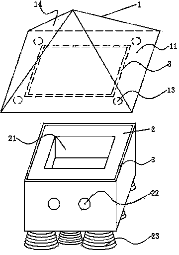
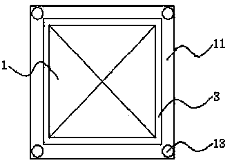
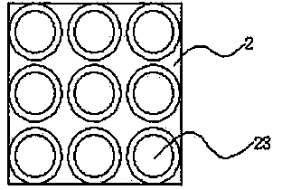
[0019] see Figure 1-4 , the specific embodiment is realized by adopting the following technical scheme, which includes a top cover 1 and a cushion pad 2 connected thereto, the top cover 1 and the cushion pad 2 are fixed by the zipper 3 interengaging, and fit the cushion pad 2 The outer profile of the top cover 1 extends outwards with a flash 11, the flash 11 is provided with an air collecting hole 13, and its surroundings are provided with a deceleration parachute 14 that fits the edge for sealing, and the other side of the top cover 1 is provided with a zipper 3, And the periphery of slide fastener 3 is provided with air-collecting hole ...


PUM


Abstract

The invention discloses an extreme low-altitude drop device which comprises a top cover and a cushion connected with the top cover. The top cover is intermeshed and fixed with the cushion through zippers, and a fin extends out of the top cover along the external contour of the cushion. Air accumulating holes are formed in the fin, and a speed reducing umbrella which is fitted with an edge of the fin to seal and fix is arranged around the fin. A zipper is arranged on the other surface of the top cover, and air accumulating holes are formed in the periphery of the zipper. The whole cushion is in a hollow structure, a concave-inward material groove is formed in the top surface of the cushion, intermeshed zippers are arranged on the surrounding edges of the cushion, and a shock absorption device is arranged on the bottom surface of the cushion. The extreme low-altitude drop device can effectively realize extreme low-altitude air drop under harsh environmental conditions such as high wind, rainfall, complex terrain conditions and the like, can avoid the influence of disturbance airflow, can realize fixed point precise air drop to fill the domestic blank in the field, and is also beneficial to recovery for secondary utilization after air drop.

Description

technical field [0001] The invention relates to the field of airdrop technology, in particular to an ultra-low altitude drop device. Background technique [0002] In emergency rescue, disaster relief or wartime, the transportation of necessities such as food, daily necessities, medical equipment and ordnance is crucial, among which the airborne airdrop method is widely used because of its fast characteristics. However, in various harsh and complex environments, high-altitude airdrop equipment will be affected by turbulent airflow, making it difficult to achieve precise airdrops at fixed points, and materials airdropped to the ground will also be subject to greater impact, which can easily cause damage or shock damage to the goods The phenomenon. [0003] However, if ultra-low-altitude delivery is used, although precise airdrops can be effectively achieved, due to the complex terrain and turbulent airflow in the low-altitude environment, the parachute often does not open in ...

Claims


Application Information

Patent Timeline
IPC IPC(8): B64D1/14B64D17/78
Inventor 李明骏
Owner JINLING INST OF TECH
Learn More