Sludge forming machine
A molding machine and sludge technology, which is applied to material molding presses, dehydration/drying/concentrated sludge treatment, presses, etc., can solve problems such as low work efficiency, reduce manpower, time-consuming and laborious, and achieve convenient cleaning And replacement, not easy to block, to achieve the effect of large-scale production
- Summary
- Abstract
- Description
- Claims
- Application Information
AI Technical Summary
Problems solved by technology
Method used
Image

Examples
Embodiment 1
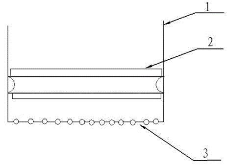
[0019] Embodiment one: a kind of sludge molding machine designed by the present invention, refer to figure 1 , its structure includes a sludge bin 1 and an extruding device 2. The extruding device is fixed horizontally inside the sludge bin. The top opening of the sludge bin forms a feed inlet, and the bottom plate is opened with a plurality of round holes to form a discharge outlet. 3. The sludge enters the sludge bin from the feed port, and the extrusion device applies pressure to the sludge to make the sludge go out from the discharge port. The round hole on the bottom plate ensures the shape of the sludge.
Embodiment 2
[0020] Embodiment 2: A sludge molding machine designed by the present invention, its structure includes a sludge bin and an extruding device, the extruding device is fixed in the sludge bin in a horizontal direction, and the top opening of the sludge bin forms a feed The bottom plate is provided with a plurality of round holes to form a discharge port, and the above-mentioned structure is the same as that of the first embodiment.
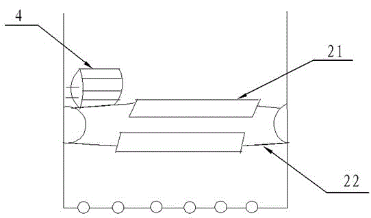
[0021] For the structure of the extruding device, refer to figure 2 , including a rolling shaft A21 and a scraper 22, the scraper is fixed on the rolling shaft A, and the first and last ends of the rolling shaft A are fixed on the inner wall of the sludge bin.
[0022] The variable frequency motor E4 is fixed on the rolling shaft A.
Embodiment 3
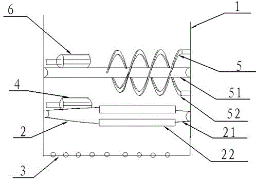
[0023] Embodiment three: a kind of sludge shaping machine that the present invention designs, as image 3 As shown, its structure includes a sludge bin and an extruding device. The extruding device is fixed inside the sludge bin in a horizontal direction. The top opening of the sludge bin forms a feed inlet, and the bottom plate has multiple round holes to form a discharge port. .
[0024] The structure of the extrusion device includes a rolling shaft A and a scraper, the scraper is fixed on the rolling shaft A, and the first and last ends of the rolling shaft A are fixed on the inner wall of the sludge bin.
[0025] The variable frequency motor E is fixed on the rolling shaft A.
[0026] Fix the agitating device 5 above the extruding device, the agitating device is parallel to the extruding device, and the distance between the agitating device and the extruding device is 400-450mm.
[0027] The structure of the stirring device includes a rolling shaft B51 and double helical...
PUM
 Abstract
Description
Claims
Application Information
 - R&D
- Intellectual Property
- Life Sciences
- Materials
- Tech Scout
- Unparalleled Data Quality
- Higher Quality Content
- 60% Fewer Hallucinations
Browse by: Latest US Patents, China's latest patents, Technical Efficacy Thesaurus, Application Domain, Technology Topic, Popular Technical Reports.
© 2025 PatSnap. All rights reserved.Legal|Privacy policy|Modern Slavery Act Transparency Statement|Sitemap|About US| Contact US: help@patsnap.com