
A method for determining the limit working torque of drill tool joints under complex working conditions

A technology of ultimate working torque and drill tool joints, which is applied to drill pipes, drill pipes, drilling equipment, etc., which can solve the problem of difficult to reflect the torsional strength of downhole drilling tools, difficult to reflect the limit working torque of drill tool joints, and difficult to evaluate the force characteristics. And other issues

Active Publication Date: 2016-01-13
SHANGHAI UNIV
View PDF3 Cites 0 Cited by
  • Summary
  • Abstract
  • Description
  • Claims
  • Application Information

AI Technical Summary

Problems solved by technology

However, the two-dimensional axisymmetric model is difficult to evaluate the force characteristics of the tool joint under complex working conditions such as make-up torque and bending moment, so it is also difficult to reflect the ultimate working torque of the tool joint
[0004] Although the API standard provides the torsional strength of the drill tool joint, it fails to consider the load conditions such as axial tension and bending moment, so it is difficult to reflect the torsional strength of the downhole drilling tool under real working conditions

Method used


Image

  • A method for determining the limit working torque of drill tool joints under complex working conditions
  • A method for determining the limit working torque of drill tool joints under complex working conditions
  • A method for determining the limit working torque of drill tool joints under complex working conditions

Examples


Embodiment

[0027] Example: Determination of Limit Working Torque of Drill Tool Joint Using Three-Dimensional Finite Element Analysis Technique

[0028] Using this evaluation method to evaluate a certain drill joint, the main parameters of the drill joint are shown in Table 1.

[0029]

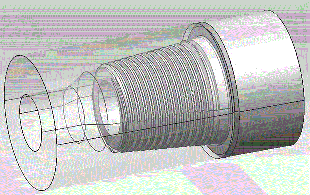
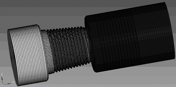
[0030] Use CAD geometric modeling software to establish a three-dimensional geometric model of the drill tool joint, such as figure 1 shown. Use the finite element pre-processing software to mesh the drill joint, and establish a three-dimensional finite element model of the threaded joint, as shown in figure 2 shown.

[0031] The material used for the tool joint is an isotropic elastic-plastic material with an elastic modulus of 2.06×10 5 MPa, Poisson's ratio is 0.29, and the true stress-plastic strain data of the material are shown in Table 2. Considering the influence of thread grease containing 40-60% by weight of zinc powder, the coefficient of friction between mating surfaces (including bet...


PUM


Abstract

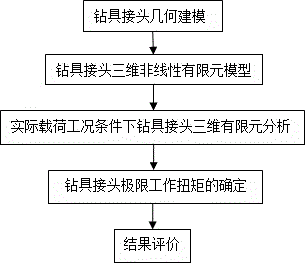
The invention provides a method for determining the limit working torque of a drill tool joint under complex working conditions, which uses finite element pre-processing software to divide the three-dimensional geometric model of the drill tool joint into grids, establishes a three-dimensional finite element model of the drill tool joint, and uses The nonlinear finite element analysis software ABAQUS performs calculations to obtain the mechanical properties of the downhole drill joint under actual load conditions. And on this basis, calculate the ultimate working torque that the drill joint can bear. This evaluation method can evaluate the ultimate working torque of the drill tool joint under complex external loads such as make-up torque, axial tension, and bending moment, so as to evaluate the safety of the drill tool joint. It is of great significance to recognize the load limit of the tool joint, guide the improvement of the structural parameters of the tool joint and the selection of working parameters, and ensure the safety of drilling operations.

Description

technical field [0001] The invention relates to the technical field of oilfield drilling, in particular to a method for determining the limit working torque of a drill tool joint under complex working conditions. Background technique [0002] Drilling tools are the main tools used to transmit power and transport drilling fluid, and play an important role in the drilling process of oil and gas fields. Drilling tool failure accidents often bring huge economic losses to oil fields. According to the statistical analysis of drill string failure accidents, 65% of the failure accidents occurred at the drill pipe joints. With the number of deep wells, ultra-deep wells and extended-reach horizontal wells increasing year by year, the torsional performance of drill tool joints has received more and more attention. In particular, when encountering the complex working conditions of downhole stuck pipe, due to the large axial load, if it is necessary to choose the measure of rotating the...

Claims


Application Information

Patent Timeline
Patent Type & Authority Patents(China)
IPC IPC(8): E21B17/02
Inventor 狄勤丰陈锋李宁朱卫平王文昌王明杰
Owner SHANGHAI UNIV
Learn More